background image

ii

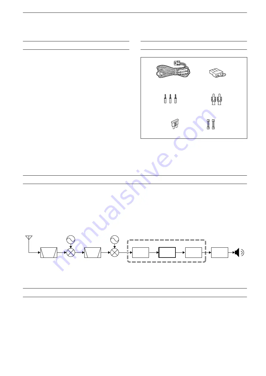
While ordinary wide band receivers need to have dedicated demodulator circuits for each receive mode, the IC-

R8600 utilizes advanced digital processes that demodulate the incoming signals.

The IF signal is sent to the A/D converter, resulting in digital signal, then is processed by a high-speed FPGA and 

DSP to be restored to an analog audio signal.

The received signal is processed to be demodulated according to the receive mode, including not only conventional 

analog communications in CW, AM, SSB, FM, WFM and FSK, but also advanced digital communications in D-STAR, 

P25, NXDN, dPMR and DCR. This was archived by using Software Defined Radio (SDR) technology.

The AMBE+2™ voice coding Technology embodied in this product is protected by intellectual property rights 

including patent rights, copyrights and trade secrets of Digital Voice Systems, Inc. This voice coding Technology is 

licensed solely for use within this Communications Equipment. The user of this Technology is explicitly prohibited 

from attempting to extract, remove, decompile, reverse engineer, or disassemble the Object Code, or in any other 

way convert the Object Code into a human-readable form. U.S. Patent Nos.

#5,870,405, #5,826,222, #5,754,974, #5,701,390, #5,715,365, #5,649,050, #5,630,011, #5,581,656, #5,517,511, 

#5,491,772, #5,247,579, #5,226,084 and #5,195,166.

FEATURES


Covers 10 kHz to 3 GHz for wide band reception


 Receives various digital modes such as  

D-STAR, P25 (Phase 1), NXDN, dPMR and DCR 

(Digital Convenience Radio)


12 kHz IF output port for DRM broadcast


Hi-speed Real-Time Spectrum Scope


A 4.3 inch touch panel color display


Multi-function dials for easy settings


An SD card slot

   You can record the received audio, save the receiver 

settings, decoded FSK logs and so on, onto an SD card 

(user supplied).


“IP+” Function

    The IP Plus function improves 3rd order intercept point 

(IP3) performance.


I/Q baseband signal output port


 Optional external speaker (with integrated power 

supply)

SUPPLIED ACCESSORIES

ABOUT THE SDR WIDEBAND RECEIVER CIRCUITS

VOICE CODING TECHNOLOGY

L

 Different types of accessories may be supplied, or may 

not be supplied depending on the receiver version.

DC power cable

(3 m: 9.8 ft)

Spare fuse  

(3 A/32 V)

Spare fuse  

(3 A/125 V)

Speaker plugs

(3.5 mm: 1/8" Stereo)

RCA plugs

DC power short connector

FPGA

BPF

BPF

A/D

DSP

D/A

1st LO

2nd LO

IF

Demodulator

Double conversion super heterodyne receiver (Example for 30.000000 MHz ~ 1099.999999 MHz)

Summary of Contents for IC-R8600

Page 1: ...INSTRUCTION MANUAL iR8600 COMMUNICATIONS RECEIVER...

Page 2: ...the design of your IC R8600 This product includes RTOS RTX software and is licensed according to the software license This product includes zlib open source software and is licensed according to the o...

Page 3: ...her way convert the Object Code into a human readable form U S Patent Nos 5 870 405 5 826 222 5 754 974 5 701 390 5 715 365 5 649 050 5 630 011 5 581 656 5 517 511 5 491 772 5 247 579 5 226 084 and 5...

Page 4: ...h the receiver is connected Consult the dealer or an experienced radio TV technician for help DISPOSAL The crossed out wheeled bin symbol on your product literature or packaging reminds you that in th...

Page 5: ...th When you wipe the touch screen be careful not to push it too hard or scratch it with your finger nails Otherwise you may damage the screen ABOUT THE INSTRUCTIONS Instruction example MENU SET Time S...

Page 6: ...the Tuning Step TS function 3 2 D D About the Programmable Tuning Step function 3 3 D DAbout the Auto Tuning Step function 3 3 Selecting the antenna 3 3 Dial Panel Lock function 3 3 D DDial Lock funct...

Page 7: ...group memory name 8 4 D DEntering a group name 8 4 D DEntering a memory name 8 4 About the MEMORY screen 8 5 9 SCANS 9 1 Scan types 9 1 Basic scanning 9 1 D DVFO scan and Memory scan 9 1 D DPriority s...

Page 8: ...Resetting 12 2 D DPartial reset 12 2 D DAll reset 12 2 Touch screen calibration 12 3 Troubleshooting 12 4 13 UPDATING THE FIRMWARE 13 1 General 13 1 D DAbout updating the firmware 13 1 D DChecking th...

Page 9: ...ould cause an injury or damage the receiver R WARNING NEVER operate the receiver during a lightning storm It may result in an electric shock cause a fire or damage the receiver Always disconnect the p...

Page 10: ...o tone Treble or Bass Hold down to turn ON the Monitor function the squelch opens i SD CARD SLOT SD CARD pp 7 1 7 2 Accepts an SD card o MENU KEY pp 1 6 11 1 Opens the MENU screens where you can modif...

Page 11: ...to toggle between the VFO and Memory modes Hold down for 1 second to copy the selected memory channel contents to the VFO 2 MEMORY GROUP KEY p 8 1 Changes the Memory channel group 3 DIAL C p 1 6 Push...

Page 12: ...2EXTERNAL SPEAKER JACK EXT SP pp 2 3 16 2 Connects to an optional external speaker SP 39AD External speaker with built in power adapter 3 5 mm 1 8 in d LAccepts a 4 8 speaker 3AF IF OUTPUT JACK AF IF...

Page 13: ...ENUATOR INDICATOR ATT10 ATT20 ATT30 pp 1 7 5 1 Is displayed while the attenuator is ON i IP ICON pp 1 7 5 2 Is displayed while the IP Plus function is ON This screen is only an example o NETWORK CONTR...

Page 14: ...6 OVERFLOW OVF INDICATOR pp 3 1 5 1 Is displayed when an excessively strong signal is received Normally S is displayed to in the S Meter mode 7 AGC INDICATOR pp 1 7 5 1 Displays the selected AGC time...

Page 15: ...otate When holding down for 1 second LTouch an item When holding down for 1 second The Monitor function is turned ON RECEIVE lights green LRelease to turn OFF the Monitor function D DQUICK MENU z z Pu...

Page 16: ...OFF or UC AGC 1 FAST MID or SLOW NOTCH 1 OFF AN or MN NB 1 OFF or ON SCRAM 1 OFF or ON ENCRYP 1 OFF or ON NR 1 OFF or ON DUP 1 OFF DUP or DUP Category Edit items Total character number Selectable cha...

Page 17: ...r case entry mode 6 Enter a name of up to 16 characters then touch ENT The entered name is displayed D DKeyboard types You can select the Full Keyboard or Tenkey in Keyboard Type in the QUICK MENU 1 W...

Page 18: ...olding the stand dials controls and so on This may damage them Heat dissipation Grounding To prevent electrical shock interfere from other electric devices and other problems ground the receiver using...

Page 19: ...vice or network settings You can change the FSK output port on the MENU screen You can download the USB driver and installation guide from the Icom website http www icom co jp world support download f...

Page 20: ...l meter Outputs the In phase Quadrature I Q data Inputs the Mute control signal Used for the Bit Error Rate BER measurement function REMOTE jack p 16 2 3 5 mm 1 8 in d EXT SP External speaker jack p 1...

Page 21: ...or DIGITAL mode A higher level blocks weak signals A lower level allows you to hear weak signals including noise L While the squelch is closed the noise audio is muted and the RECEIVE indicator is OFF...

Page 22: ...ator 2 Touch to select the tuning step Example 20k The tuning step is set and returns to the previous screen LInformatio L S Synchronous AM mode The Synchronous AM demodulation is a receive method tha...

Page 23: ...TION QUICK menu Set mode or Scan Start screen is displayed LYou can change this setting on the MENU screen MENU SET Function SPEECH LOCK Switch D DPanel Lock function The Panel Lock function locks all...

Page 24: ...FM mode and when the AFC function is ON the marker may not be steady in the center position D DWhen receiving FSK signal You can have a fine tuning into the signal by tuning to where both and are disp...

Page 25: ...reen Function menu Menu 2 z z Touch 1 to switch to Menu 2 D DRX Marker In the Fixed mode the RX Marker always marks the receive frequency on the SPECTRUM SCOPE screen L The marker marks the receive fr...

Page 26: ...0 010 3000 000 MHz 1 Open the SPECTRUM SCOPE screen MENU SCOPE 2 Touch CENT FIX Each touch changes between the Center and Fixed mode 3 Touch EDGE 4 Touch EDIT 5 Touch to select the upper or lower edg...

Page 27: ...nter appears on the strongest signal frequency within the scope frequency range 4 To exit the peak search menu push Spectrum scope screen Continue Search menu keys Key Action SEARCH Touch to put the p...

Page 28: ...d to reset to 0 0 dB LTouch REF to return to Menu 2 5 To exit the SPECTRUM SCOPE screen push several times Difference in spectrum display Reference level 20 0 dB Reference level 20 0 dB L If you adjus...

Page 29: ...ter Displays the selected filter s center frequency in the center of the SPECTRUM SCOPE screen Carrier Point Center Displays the carrier point frequency of the selected operating mode in the center of...

Page 30: ...the Expanded scope screen the Waterfall is always displayed Waterfall Speed Default Mid Select the Waterfall speed Slow Sets the waterfall speed to Slow Mid Sets the waterfall speed to Mid Fast Sets...

Page 31: ...nstants FAST MID and SLOW for all modes except the FM and DIGITAL mode 1 Select the operating mode Example SSB 2 Push to open the FUNCTION screen 3 Touch AGC to select an AGC setting Each touch change...

Page 32: ...system performance This function optimizes the Analog Digital Converter ADC against the distortion when you receive a strong input signals It also improves the Third order Intercept Point IP3 while m...

Page 33: ...0 Hz 600 Hz to 3 6 kHz 100 Hz FIL 2 500 Hz FIL 3 250 Hz FSK FIL 1 2 4 kHz 50 Hz to 500 Hz 50 Hz 600 Hz to 2 7 kHz 100 Hz FIL 2 500 Hz FIL 3 250 Hz AM S AM FIL 1 9 0 kHz 200 Hz to 10 0 kHz 200 Hz FIL 2...

Page 34: ...R menu 3 Set the Noise Reduction level to between 0 and 15 Adjust the Noise Reduction level to where noise is reduced and the received signal is not distorted L Set to a higher level to increase the r...

Page 35: ...You can change it to USB in the CW Normal Side item of the OTHERS set screen p 11 3 MENU SET Function CW Normal Side Receiving FSK RTTY signal BFO BFO 170 Hz 1615 Hz 170 Hz 1615 Hz FSK Normal mode FSK...

Page 36: ...s and 50 bps LOG Opens the FSK DECODE LOG screen L Starts Stops logging or selects the file type LOG VIEW Opens the FSK DECODE LOG VIEW screen LYou can check the saved log files z z Touch 1 to switch...

Page 37: ...e the MENU screen push Lights while the TPF is ON NOTE When you are using the Twin Peak Filter the received audio output may increase This is not a malfunction D DFSK tone and shift setting You can ch...

Page 38: ...s for UnShift On Space function Decode New Line Code Default CR LF CR LF Select the FSK decoder new line code CR LF CR LF Makes a new line with any codes CR LF Makes a new line with only CR LF code L...

Page 39: ...range 000 FFF in hexadecimal 1 Touch D SQL on the FUNCTION screen Each touch turns the function ON or OFF 2 To change the NAC touch D SQL for 1 second Opens the DIGITAL SQL P25 screen 3 Rotate to set...

Page 40: ...the FUNCTION screen Each touch changes between COM ID CC or OFF 2 To change the COM ID or CC touch D SQL for 1 second Opens the DIGITAL SQL dPMR screen 3 Touch COM ID or CC then rotate to set the ID o...

Page 41: ...D The ID of the caller station Called ID The ID of the called station RAN UC Radio Access Number User Code Type of call ALL All GRP Group or IND Individual COM ID You can capture the receiver screen o...

Page 42: ...ed and resumes when a signal is received You can continue recording regardless of the signal presence p 6 4 If your SD card does not have an IC R8600 folder back up any data on the SD card insert it i...

Page 43: ...e skip time point Default 10 seconds Touch to pause while playing L is displayed while pausing LTo cancel the pausing touch Touch to playback the file L is displayed while pausing Operations on the Pl...

Page 44: ...eck for 1 second The QUICK MENU screen opens 4 Touch File Information 5 To close the PLAY FILES screen push EXIT several times Deleting a file You can delete the recorded audio file 1 Open the PLAY FI...

Page 45: ...s Records even if no signal is received Squelch Auto Records only when the squelch opens The recording will be paused when the squelch closes while recording File Split Default ON Turn the File Split...

Page 46: ...com will not be responsible for any damage caused by data corruption of a card You can save the following data onto the card Data settings of the receiver Memory channel contents saved in the receiver...

Page 47: ...card You can write the setting file that is saved in an earlier version to an earlier firmware version IC R8600 L Depending on the receiver s firmware version this item may not be displayed In that ca...

Page 48: ...in step 4 The new REF IN OUT REF Adjust setting will be saved is displayed 7 After the loading has been completed Restart the IC R8600 is displayed L Turn OFF the receiver power then turn ON again Del...

Page 49: ...an be programmed L The same pair of frequencies are written as the default L You cannot clear nor leave them blank D DSelecting with 1 Push V M to select the Memory mode 2 Push or to select the group...

Page 50: ...le Memory channel 04 Memory mode Group number Channel number D DSelecting with 1 Push V M to select the Memory mode 2 Rotate to select the desired memory channel D DSelecting with 1 Push V M to select...

Page 51: ...completely deleted 4 Push to close the VFO MEMORY screen You can copy the Memory contents to the VFO 1 Push V M to select the Memory mode 2 Select the memory channel to be copied 3 Hold down V M for...

Page 52: ...UP NAME editing screen is displayed 6 Enter a name of up to 10 characters L See Keyboard entering and editing p 1 8 for details 7 Touch ENT to save the entered name The MEMORY NAME screen closes and r...

Page 53: ...assign a memory name refer to page 8 4 u Select memory icon Touch this icon to set the Select number 1 9 or OFF L To clear the Select memory setting touch this icon for 1 second then select a clearing...

Page 54: ...MODE SELECT MEMORY SCAN Repeatedly scans the memory channels with the selected receive mode ignoring other receive modes p 9 9 PRIORITY SCAN Periodically monitors a selected memory channel while recei...

Page 55: ...Scan Resume function D DSetting the Scan Resume function You can set the Scan Resume options for when the signal disappears 1 Hold down for 1 second The SCAN DELAY screen opens 2 Touch the resume cond...

Page 56: ...ry channels A000 A199 before starting an MW scan Display SCAN Screen at SCAN START Default ON Selects whether or not to display the SCAN screen when you push to start a scan except Priority scan OFF D...

Page 57: ...ter and tuning step TS 5 Rotate or to touch EDIT to change the setting L The changed settings are stored in the Program Scan Edge channel 6 Touch SELECT several times to exit the edit mode then touch...

Page 58: ...tting Set the center frequency and span L The scan does not start when the tuning step is wider than the span 6 Touch SELECT several times to exit the edit mode then touch START or hold down for 1 sec...

Page 59: ...00 A199 every time you start a Auto Memory Write scan See page 9 3 for details L The channels in group A A000 A199 are automatically aligned at the top and all the blank channels are removed A000 A199...

Page 60: ...to change the setting Set the channel group and edge channels If you do not specify the group set Group to ALL 5 Touch SELECT several times to exit the edit mode then touch START The Memory scan start...

Page 61: ...t the Select scan number L Each touch changes between 1 to 9 and no icon 6 To close the VFO MEMORY screen push EXIT D D Canceling the Select Memory channel settings You can cancel the select memory se...

Page 62: ...u can set a frequency as a skip frequency that is skipped ignored during a VFO scan Programmed scan Fine Programmed scan Auto Write Memory scan F scan and Fine F scan D DSetting the skip frequency z z...

Page 63: ...skipped ignored during a VFO scan or memory scan for a period of time default 5 minutes Programmed scan Fine Programmed scan Auto Write Memory scan F scan and Fine F scan 1 Start a VFO or memory scan...

Page 64: ...ted frequency or code is automatically set 5 To cancel the scan touch T SCAN again LThe last scanned tone frequency or code is displayed 6 To close the TONE FREQUENCY screen push EXIT Blinks during sc...

Page 65: ...4 To close the Date screen push EXIT several times D DSetting time 1 Open the Time screen MENU SET Time Set Date Time Time 2 Touch or to set the current time 3 Touch SET to store the entry 4 To close...

Page 66: ...ified day and time LYou can set up to 3 timer slots for different timer setting 1 Hold down for 1 second 2 Touch to select a timer slot 3 Rotate to set each item for the timer slot Example TIMER1 LSee...

Page 67: ...ected memory channel Day of the Week Default Selects the day of the week to activate the Timer every week If you want to activate the Timer everyday push then touch Clear Repeat Setting Default OFF Se...

Page 68: ...e Set mode is constructed in a tree structure You may go to the next tree level or go back a level depending on the selected item 6 Rotate to select the desired option and then push to set it LInforma...

Page 69: ...l Limit Default ON Selects whether or not to limit the volume up to the specified level OFF Does not limit the volume level ON Limits the volume level Further rotation of does not increase the level B...

Page 70: ...ht MAIN DIAL Auto TS Default High Sets the Auto Tuning Step function for MAIN DIAL When rapidly rotating MAIN DIAL the tuning step automatically changes according to the rotation speed OFF Auto tuning...

Page 71: ...al Default Sep Dec Selects the separator and the decimal character for the CSV format Sep Dec Separator is and Decimal is Sep Dec Separator is and Decimal is Sep Dec Separator is and Decimal is L The...

Page 72: ...the AF output level of USB on the front panel Range 0 100 MENU SET Connectors USB Front AF SQL Default OFF OPEN Selects whether or not to output the audio from USB on the front panel according to the...

Page 73: ...s OFF OPEN The squelch is always opened regardless of the squelch and signal levels ON The squelch opens and closes according to the squelch and signal levels LAN AF Speech Output Default OFF Sets the...

Page 74: ...e signal NOTE SELECT OFF or OUT if you are not use a reliable external signal source When the input signal source level is too low or the frequency precision is not high the fre quency readout blinks...

Page 75: ...03 When you remotely control the IC R8600 using the op tional RS R8600 future product set a port number for the audio signal transfers between the IC R8600 and the remote station LThis setting takes e...

Page 76: ...splay RX Popup Default Normal Selects whether or not to display the information included in the received digital signal such as call sign caller s ID code and so on when you receive a digital signal O...

Page 77: ...data write details SD Card Info Displays the SD card capacity and the time remaining for recording Screen Capture View Displays the selected screen capture L See Screen Capture function p 5 11 for de...

Page 78: ...cable and the circuitry in the body to protect the receiver DC power cable fuses 3 A 125 V Circuitry fuse ATC 3 A 32 V RWARNING Disconnect the DC power cable from the receiver before replacing the fus...

Page 79: ...Opening comments are not returned to their default value 1 Open the RESET screen MENU SET Others Reset 2 Touch Partial reset The confirmation screen is displayed 3 Touch Yes L After resetting the IC...

Page 80: ...that appears on the screen A new dot appears in another position 4 Repeat step 3 L When the calibration is complete the receiver returns to the OTHERS screen 5 Touch the frequency readout or key on th...

Page 81: ...d to EX SP or PHONES Disconnect the headphones p 2 3 The external speaker cable is disconnected Check the external speaker cable and repair it p 2 3 Sensitivity is too low and only strong signals can...

Page 82: ...nking No external reference signal is input Check the REF I O 10MHz connector setting or external signal source p 11 7 OVF is displayed An excessively strong signal is received Set RF GAIN to a lower...

Page 83: ...ructions are based on Microsoft Windows 7 1 Click Support 2 Click Firmware Updates Software Downloads 3 Click the desired firmware file link 4 Read Regarding this Download Service carefully and then c...

Page 84: ...ard into the receiver s SD CARD slot 3 On the Set mode menu screen display the SD CARD screen MENU SET SD card 4 Select Firmware Update The Firmware Update Agreement screen Copy TIP To check the rmwar...

Page 85: ...ystem Negative Operating temperature range 10 C to 60 C 14 F to 140 F Frequency stability Less than 0 5 ppm Antenna connectors Frequency resolution 1 Hz minimum Power consumption Standby 1 8 A Maximum...

Page 86: ...AL D STAR NXDN dPMR and DCR 28 000000 1099 999999 MHz 1 BER 2 dB P AMP ON 1100 000000 1999 999999 MHz 1 BER 2 dB P AMP ON 2000 000000 3000 000000 MHz 1 BER 0 dB P AMP ON DIGITAL P25 28 000000 1099 999...

Page 87: ...z z MB 123 Carrying handle z z RS R8600 Remote control software Future product z z CS R8600 Programming Software Attaching the MB 123 R WARNING NEVER use other than the screws supplied with the MB 123...

Page 88: ...nal or D STAR data Outputs the demodulated signal or 12 kHz IF signal Remote control interface for optional RS R8600 feature product Programming interface for the optional CS R8600 L You can change th...

Page 89: ...C13 8V DC13 8V Accepts the regulated DC power for 13 8 V DC 15 through the supplied DC power cable WARNING NEVER reverse the DC power cable polarity Red Black ANT 1 Frequency range 10 kHz 3000 MHz Inp...

Page 90: ...LARY OR CONSEQUENTIAL DAMAGES INCLUDING BUT NOT LIMITED TO PROCUREMENT OF SUBSTITUTE GOODS OR SERVICES LOSS OF USE DATA OR PROFITS OR BUSINESS INTERRUPTION HOWEVER CAUSED AND ON ANY THEORY OF LIABILIT...

Page 91: ...ess 11 6 Baud Rate 11 6 Baud Rate Front USB port 11 6 Baud Rate Rear USB port 11 7 Echo Back Front USB port 11 6 Echo Back Rear USB port 11 7 Port Rear USB port 11 7 Transceive 11 6 Cleaning 12 1 Cloc...

Page 92: ...14 1 Front panel 1 1 FSK RTTY Decode 5 5 Decoder 2 2 Decode Baud Rate 11 5 11 6 DECODE SET screen 5 8 Decode setting 5 8 Logging 5 6 Log view 5 7 Receiving FSK RTTY signal 5 5 Shift setting 5 7 Tone a...

Page 93: ...work User Administrator 11 8 Network User ID 11 8 Network User Password 11 8 Primary DNS Server 11 7 Serial Port UDP 11 8 Subnet Mask 11 7 Transceive Address 11 6 Noise Blanker NB 5 4 Noise reduction...

Page 94: ...rameters 4 5 Scope set screen 4 5 Waterfall zone 4 3 Screen Screen Capture File Type 11 4 Screen Capture function 5 11 Screen Capture POWER Switch 11 3 Screen Capture View 11 10 Screen Saver 11 9 Touc...

Page 95: ...ontrol 11 2 Tone frequencies 5 9 Tone scan operation 9 11 Tone squelch function 5 9 Touch panel display 1 4 Touch screen calibration 11 10 12 3 Touch screen operation 4 3 TRADEMARKS i Treble 11 2 Trou...

Page 96: ...Inc Intended Country of Use AT FI IT PL GB RO BE FR LV PT IS TR CY DE LT SK LI HR CZ GR LU SI NO DK HU MT ES CH EE IE NL SE BG Intended Country of Use AT FI IT PL GB RO BE FR LV PT IS TR CY DE LT SK...

Reviews: