background image

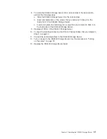
c.


Close


both


handles


and


snap


into


place.

5.


Using


Figure


35


as


a


guide,


check


the


controller


indicator


lights.


v


If


the


green


power


indicator


light


is


on


and


the


amber


fault


indicator


light


is


off,


go


to


Step


8.


v


If


the


green


power


indicator


light


remains


off


or


the


fault


indicator


light


is


on


after


a


few


seconds,


make


sure


that


the


controller


CRU


is


locked


into


place.


If


the


fault


indicator


light


remains


on,


go


to


Step


6.

6.


Use


the


storage-management


software


to


check


the


status


of


both


controllers.


If


applicable,


perform


the


recovery


procedures


required


by


the


software.


If


this


corrects


the


fault


and


the


DS4500


Storage


Server


is


operating


without


error,


go


to


Step


8.


If


not,


go


to


Step


7.


7.


Reinsert


the


controller


CRU.


Then,


if


there


are


no


error


messages


or


controller


faults,


go


to


Step


8.


If


there


is


still


a


problem,


call


for


service.


8.


Replace


the


DS4500


Storage


Server


bezel,


as


shown


in


Figure


22


on


page


22.

Battery


The


battery


CRU


contains


rechargeable


batteries


and


a


battery-charger


board.


The


battery


CRU


plugs


into


the


front


of


the


DS4500


Storage


Server


(see


Figure


36


on


page


48)


where


it


provides


backup


power


to


the


cache


memory


in


both


controllers.


During


a


power


outage,


a


properly


charged


battery


CRU


maintains


electrical


current


to


the


controllers


for


up


to


five


days


with


1


Gb


cache


memory


installed.


All


data


stored


in


memory


is


preserved


as


long


as


the


batteries


can


sustain


power


to


the


cache


memory.


However,


the


battery


does


not


provide


power


to


the


rest


of


the


system


during


a


power


outage.


Therefore,


the


system


is


not


able


to


write


data


to


hard


disk


drives


without


a


backup


power


source.


Servicing


notes


Consider


the


following


factors


when


you


service


the


battery


in


the


DS4500


Storage


Server:


v


The


battery


has


a


three-year


life


expectancy.


Replace


the


battery


every


three


years


or


whenever


it


fails


to


hold


a


charge.


Operating


the


DS4500


Storage


Server


in


an


unsupported


environment


(above


35°


C


or


95°


F)


lowers


the


life


expectancy


of


the


battery.


v


The


service


label


on


the


battery


provides


a


blank


line


for


recording


the


date


on


which


the


battery


was


last


serviced


(see


Figure


37


on


page


49).


Check


this


label


to


determine


when


to


replace


the


battery.


For


information


about


using


the


software


to


track


battery


age,


refer


to


the


IBM


DS4000


Storage


Manager


online


help.


Figure


35.


Indicator


lights


on


the


DS4500


Storage


Server


bezel


46


IBM


TotalStorage


DS4500


Fibre


Channel


Storage


Server:


User’s


Guide

Summary of Contents for TotalStorage DS4500

Page 1: ...IBM TotalStorage DS4500 Fibre Channel Storage Server User s Guide GC26 7726 00...

Page 2: ......

Page 3: ...IBM TotalStorage DS4500 Fibre Channel Storage Server User s Guide GC26 7726 00...

Page 4: ...the general information under Notices on page 69 First Edition January 2005 Copyright International Business Machines Corporation 2005 All rights reserved US Government Users Restricted Rights Use du...

Page 5: ...Fire suppression systems xxviii How to send your comments xxviii Chapter 1 Introduction 1 DS4500 Storage Server overview 1 Product updates 1 Front view 2 Back view 3 Fibre Channel connections 4 Handl...

Page 6: ...ervicing notes 46 Replacing a failed battery 47 Storage server fan 50 Servicing notes 51 Replacing a failed storage server fan 52 Fan and communications module 53 Servicing notes 54 Replacing a failed...

Page 7: ...Glossary 75 75 Index 85 Contents v...

Page 8: ...vi IBM TotalStorage DS4500 Fibre Channel Storage Server User s Guide...

Page 9: ...ower switch locations 23 24 Storage server indicator lights 27 25 RAID controller indicator lights 29 26 Battery indicator lights 30 27 Fan and communications module indicator light 31 28 Power supply...

Page 10: ...viii IBM TotalStorage DS4500 Fibre Channel Storage Server User s Guide...

Page 11: ...age DS4000 Storage Manager Version 9 titles by user tasks xxiii 7 TotalStorage DS4000 and DS4000 related document titles by user tasks xxiv 8 Possible combinations of FAStT EXP500 and DS4000 EXP700 st...

Page 12: ...x IBM TotalStorage DS4500 Fibre Channel Storage Server User s Guide...

Page 13: ...lleert eerst de veiligheidsvoorschriften Ennen kuin asennat t m n tuotteen lue turvaohjeet kohdasta Safety Information Avant d installer ce produit lisez les consignes de s curit Vor der Installation...

Page 14: ...hed to this product v When possible use one hand only to connect or disconnect signal cables v Never turn on any equipment when there is evidence of fire water or structural damage v Disconnect the at...

Page 15: ...nto water v Heat to more than 100 C 212 F v Repair or disassemble Dispose of the battery as required by local ordinances or regulations Statement 3 CAUTION When laser products such as CD ROMs DVD driv...

Page 16: ...on when open Do not stare into the beam do not view directly with optical instruments and avoid direct exposure to the beam Class 1 Laser Statement Statement 4 18 kg 39 7 lb 32 kg 70 5 lb 55 kg 121 2...

Page 17: ...from the device ensure that all power cords are disconnected from the power source 1 2 Statement 8 CAUTION Never remove the cover on a power supply or any part that has the following label attached Ha...

Page 18: ...xvi IBM TotalStorage DS4500 Fibre Channel Storage Server User s Guide...

Page 19: ...th new names are functionally equivalent and fully interoperable Each DS4000 product retains full IBM service as outlined in service contracts issued for analogous FAStT products Table 1 Mapping of FA...

Page 20: ...SW on Host and Workstation FC Planning and Integration User s Guide and Svc Info DS4000 Storage Manager Concepts Guide DS4000 Storage Exp Units Install and User s Guides DS4000 Fibre Channel Storage S...

Page 21: ...e 2 TotalStorage DS4500 Fibre Channel Storage Server document titles by user tasks Title User Tasks Planning Hardware Installation Software Installation Configuration Operation and Administration Diag...

Page 22: ...tasks Title User Tasks Planning Hardware Installation Software Installation Configuration Operation and Administration Diagnosis and Maintenance IBM DS4400 Fibre Channel Storage Server User s Guide GC...

Page 23: ...iguration Operation and Administration Diagnosis and Maintenance IBM TotalStorage DS4300 Fibre Channel Storage Server Installation and User s Guide GC26 7722 U U U IBM TotalStorage DS4300 Rack Mountin...

Page 24: ...Storage Server document titles by user tasks Title User Tasks Planning Hardware Installation Software Installation Configuration Operation and Administration Diagnosis and Maintenance IBM TotalStorage...

Page 25: ...tion and administration Diagnosis and maintenance IBM TotalStorage DS4000 Storage Manager Version 9 Installation and Support Guide for Windows 2000 Server 2003 NetWare ESX Server and Linux GC26 7706 U...

Page 26: ...Maintenance Manual GC26 7702 U IBM TotalStorage DS4000 Problem Determination Guide GC26 7703 U IBM Fibre Channel Planning and Integration User s Guide and Service Information SC23 4329 U U U U IBM Tot...

Page 27: ...ser s Guide 32P0081 U U IBM Netfinity Fibre Channel Cabling Instructions 19K0906 U IBM Fibre Channel SAN Configuration Setup Guide 25P2509 U U U U How this document is organized Chapter 1 Introduction...

Page 28: ...find a wide variety of sources available from IBM to assist you This section contains information about where to go for additional information about IBM and IBM products what to do if you experience...

Page 29: ...hrough the IBM Publications Ordering System at the following web site www elink ibmlink ibm com public applications publications cgibin pbi cgi v For the latest information about IBM xSeries products...

Page 30: ...ment to internal and external standards that require certain environments for reliable operation Because IBM does not test any equipment for compatibility with fire suppression systems IBM does not ma...

Page 31: ...r supports a maximum of 224 hard drives when the drives are configured using IBM DS4000 EXP700 DS4000 EXP710 or DS4000 EXP100 storage expansion enclosures If the drives are configured using IBM FAStT...

Page 32: ...your DS4000 series product as well as any other attached DS4000 series product s for which you would like to receive information Select Add products The My support page reopens 4 Select Subscribe to e...

Page 33: ...hts Back view Figure 4 on page 4 shows the DS4500 Storage Server back view and the following components v Host side and drive side mini hubs Up to eight removable mini hubs with indicator lights You c...

Page 34: ...ide mini hubs Each mini hub is a single removable unit that provides the Fibre Channel interface between a DS4500 Storage Server host computers and drives Each mini hub has two SFP module ports An SFP...

Page 35: ...1 5 in when extended or become pinched when retracted v Route the cable away from places where it can be damaged by other devices in the rack cabinet v Do not use plastic cable ties in place of the pr...

Page 36: ...DVD drives fiber optic devices or transmitters are installed note the following precautions v Do not remove the covers Removing the covers of the laser product could result in exposure to hazardous l...

Page 37: ...future use 4 Carefully insert that same end of the LC LC cable into an SFP module that is installed in a DS4500 Storage Server mini hub The cable connector is keyed to ensure it is inserted into the...

Page 38: ...e Channel cable from an SFP module To remove an LC LC Fibre Channel cable perform the following steps Attention To avoid damaging the LC LC cable or SFP module make sure you press and hold the lever t...

Page 39: ...connect the LC connector into one of the following devices that require SC connectors v DS4000 host adapter Part number 00N6881 v FAStT EXP500 storage expansion enclosure Machine type 3560 v 1 Gb Fib...

Page 40: ...covers of the laser product could result in exposure to hazardous laser radiation There are no serviceable parts inside the device v Use of controls or adjustments or performance of procedures other t...

Page 41: ...into place 5 Connect the SC connector end of the LC SC cable to one of the following devices v Optical interface connector on an IBM DS4000 Host Bus Adapter Part number 00N6881 v GBIC installed in a...

Page 42: ...ctor and not the cable when you remove the LC LC cable from the LC SC cable adapter as shown in Figure 16 3 Replace the protective caps on the cable ends Types of interface ports The DS4500 Storage Se...

Page 43: ...ect to the top controller Controller A and mini hubs 2 and 4 connect to the bottom controller Controller B as shown in Figure 18 To ensure redundancy you must connect each host to both controllers thr...

Page 44: ...Storage Server controller firmware must be at version 06 xx xx xx or higher In addition you must purchase the FC SATA Enclosure Intermix premium option to combine DS4000 EXP100s with DS4000 EXP700s or...

Page 45: ...this cabling scheme If you are intermixing FAStT EXP500s and DS4000 EXP700s your drive loop configuration must meet the following requirements v The maximum Fibre Channel transfer speed in all of the...

Page 46: ...P710s must be grouped together Important The requirements for intermixing DS4000 EXP710s and EXP700s state that all DS4000 EXP710s in a redundant drive loop must be grouped together IBM does not suppo...

Page 47: ...For more information on the cabling requirements and best practices for intermixing EXP100s with EXP700s or EXP710s in the same DS4500 Storage Server configuration refer to the IBM TotalStorage DS4000...

Page 48: ...Figure 20 shows the location of the interface ports Figure 20 Ethernet interface ports 18 IBM TotalStorage DS4500 Fibre Channel Storage Server User s Guide...

Page 49: ...on other than the logical drives created for the DS4500 storage server v Ensure that your system is in an optimal state before you shut it down Never turn the power off if any fault light is lit be su...

Page 50: ...nformation to thoroughly diagnose and repair the unit Therefore it is important to use the storage management software to continuously monitor the status of the DS4500 Storage Server Checking the indi...

Page 51: ...pproximately 5 cm 2 in 1 Carefully pull the bottom of the bezel out to release the pins Then slide the bezel down as shown in Figure 21 2 To replace the bezel slip the top edge of the bezel under the...

Page 52: ...after an emergency shutdown or power outage go to Overtemperature condition and power supply shutdown on page 37 Use the following procedure to turn on the connected devices and the DS4500 Storage Ser...

Page 53: ...m on the host server perform either a server power cycle a server restart or a rescan for hardware on the host server Turning off the power Attention The DS4500 Storage Server is designed to run conti...

Page 54: ...for the drive indicator lights to stop blinking b Use the operating system software to disconnect the DS4500 Storage Server logical drives from the host before you power off the storage server c Make...

Page 55: ...prevent data loss For more information about the DS4500 Storage Manager software refer to the Online help or publications that are appropriate for your operating system see About this document on page...

Page 56: ...ntly Wait until the DS4500 Storage Server completes its power up before checking for faults It can take up to 15 minutes for the battery to complete its self test and up to 24 hours to fully charge pa...

Page 57: ...light indicates a fan fault Normal status Off Problem status On Controller Amber light indicates a controller fault Normal status Off Problem status On Fast Write Cache Green light indicates data in c...

Page 58: ...Amber Off On v The storage server fan has failed v The fan and communications module is missing unplugged or has failed v The storage server fan circuitry has failed v The temperature of the DS4500 St...

Page 59: ...ights remove the DS4500 Storage Server bezel as shown in Figure 21 on page 21 Table 11 on page 30 describes the DS4500 RAID controller indicator lights Figure 25 RAID controller indicator lights Chapt...

Page 60: ...ition2 If any status indicator lights are lit and the controller is not offline there is a memory fault indicating that the controller CRU has failed 1 Always use the storage management software to id...

Page 61: ...of charging Fan and communications module indicator light The fan and communications module has one indicator light as shown in Figure 27 Table 13 describes the fan and communications module indicator...

Page 62: ...the storage management software to identify the failure Mini hub indicator lights There are five indicator lights on each mini hub Figure 29 shows the host side indicator lights The drive side indica...

Page 63: ...the problem indicator None Speed Green On for 2 Gb Off for 1 Gb Not applicable Light on indicates data transfer rate of 2Gb s Light off indicates data transfer rate of 1Gb s Fault Amber Off On Mini hu...

Page 64: ...o functioning SFP modules are installed into the mini hub ports and no Fibre Channel cables are connected to them the bypass indicator light is lit If only one functioning SFP module is installed in a...

Page 65: ...to the mini hub v If no SFP module is installed the indicator will be lit v If one functioning SFP module is installed in the host side mini hub port and no Fibre Channel cable is connected to it the...

Page 66: ...n two functioning SFP modules are installed into the mini hub port and no Fibre Channel cables are connected to them the bypass indicator light is lit If only one functioning SFP module is installed i...

Page 67: ...communications module fault indicator and storage server fan indicator to light before the temperature has risen sufficiently to shut down the power supplies The storage server fan indicator light sh...

Page 68: ...the power switches on all storage expansion enclosures attached to the DS4500 Storage Server Important You must turn on the storage expansion enclosures before you turn on the DS4500 Storage Server Th...

Page 69: ...aring to move the DS4500 Storage Server Remove each component CRU before you move the DS4500 Storage Server to a new location or before you remove the chassis from its rack cabinet This precaution hel...

Page 70: ...ge Server For information about removing and replacing CRUs see Chapter 3 Replacing the DS4500 Storage Server components on page 43 5 Remove the two screws from the inside rear of the DS4500 Storage S...

Page 71: ...the remaining two screws that you removed in Step 5 on the inside rear of the DS4500 Storage Server 9 Replace all CRUs in the DS4500 Storage Server 10 Connect the interface cables and host Fibre Chann...

Page 72: ...42 IBM TotalStorage DS4500 Fibre Channel Storage Server User s Guide...

Page 73: ...tatic electricity from the package and from your body v Remove the device from its package and install it directly into your system unit without setting it down If it is necessary to set the device do...

Page 74: ...ntroller and is in a passive or offline status in the storage management software v If cache mirroring is enabled in redundant controllers and one controller fails the second controller assumes proces...

Page 75: ...failed a Using your thumbs squeeze the two center tabs and pull both controller handles outward with your fingers b Using both handles pull out on the controller to remove it Attention When you handl...

Page 76: ...backup power to the cache memory in both controllers During a power outage a properly charged battery CRU maintains electrical current to the controllers for up to five days with 1 Gb cache memory ins...

Page 77: ...outage occurs while the battery CRU is out of operation Attention When you handle static sensitive devices take precautions to avoid damage from static electricity For details about handling static s...

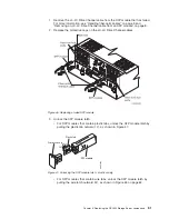
Page 78: ...CONTAINS SEALED LEAD BATTERY BATTERY MUST BE RECYCLED Pb Figure 36 Removing and installing a battery 48 IBM TotalStorage DS4500 Fibre Channel Storage Server User s Guide...

Page 79: ...h all applicable local and federal regulations 4 Prepare the new battery Unpack the battery CRU Save the packing material for shipping the used battery CRU to a disposal facility 5 Find the Battery Su...

Page 80: ...igure 41 on page 53 The dual fans in the storage server fan unit provide a redundant cooling system to both controller CRUs If one fan fails the other continues to operate providing sufficient air cir...

Page 81: ...long as you complete the exchange within 15 minutes The time limit applies to the total time that the fan is out of the chassis The time begins when you remove the failed storage server fan and ends...

Page 82: ...ut of the chassis For more information see Turning off the power on page 23 2 Remove the failed storage server fan as shown in Figure 40 a Lift up the lever on the storage server fan b Pull firmly on...

Page 83: ...erver to prevent it from overheating until you can replace the fan 6 Replace the DS4500 Storage Server bezel as shown in Figure 22 on page 22 Fan and communications module The fan and communications m...

Page 84: ...emains on replace the power supply For more information about indicator lights see Fan and communications module indicator light on page 31 and Figure 28 on page 32 v If you replace the fan and commun...

Page 85: ...00 Storage Server a Using a flat blade screwdriver loosen the two captive screws on the fan and communications module b Use the pull handle to slide the module out of the slot a few inches c Grasp the...

Page 86: ...two power supplies The power supplies slide into either of the two slots on the back of the DS4500 Storage Server The power supplies provide power to the internal components by converting incoming ac...

Page 87: ...t on the hard disk drives if they are already running and returns the DS4500 Storage Server to normal operation v When a power supply fails the green power indicator light on the power supply goes off...

Page 88: ...pply see Figure 44 on page 57 Statement 8 CAUTION Never remove the cover on a power supply or any part that has the following label attached Hazardous voltage current and energy levels are present ins...

Page 89: ...ports to attached nodes An SFP module slides into a mini hub port on the back of the DS4500 Storage Server and then a host or drive interface cable connects into the SFP module For more information s...

Page 90: ...GBICs are not supported for use in the drive ports of storage expansion enclosures Long wave SFPs and GBICs are only supported in the host ports of the DS4000 storage server Replacing a failed SFP mo...

Page 91: ...odule latch v For SFP modules that contain plastic tabs unlock the SFP module latch by pulling the plastic tab outward 10 as shown in Figure 47 v For SFP modules that contain wire tabs unlock the SFP...

Page 92: ...tabs slide the SFP module out of the port v For SFP modules that contain wire tabs grasp the wire latch and pull the SFP module out of the minihub port 5 Replace the protective cap on the SFP module 6...

Page 93: ...er see Figure 52 on page 65 A mini hub is a single removable unit that provides the Fibre Channel interface between a DS4500 Storage Server and hosts or drives The back of the DS4500 Storage Server ca...

Page 94: ...acing a failed mini hub When instructed by the storage management software replace a mini hub Use the following procedure to replace either a failed host side or drive side mini hub Attention To preve...

Page 95: ...t Then tighten the captive screw 6 Install the SFP modules that you removed in Step 4 on page 62 as follows a Remove the SFP modules from their static protective packages b Remove the protective caps...

Page 96: ...66 IBM TotalStorage DS4500 Fibre Channel Storage Server User s Guide...

Page 97: ...s v Tab Moves keyboard focus to the next component or to the first member of the next group of components v Shift Tab Moves keyboard focus to the previous component or to the first component in the pr...

Page 98: ...This behavior is the same for contiguous and non contiguous selection of drives End Page Down Move keyboard focus to the last item in the list Esc Close the current dialog does not require keyboard f...

Page 99: ...LICATION AS IS WITHOUT WARRANTY OF ANY KIND EITHER EXPRESS OR IMPLIED INCLUDING BUT NOT LIMITED TO THE IMPLIED WARRANTIES OF NON INFRINGEMENT MERCHANTABILITY OR FITNESS FOR A PARTICULAR PURPOSE Some s...

Page 100: ...the United States and other countries Java and all Java based trademarks and logos are trademarks or registered trademarks of Sun Microsystems Inc in the United States other countries or both Linux is...

Page 101: ...Federal Communications Commission FCC statement Note This equipment has been tested and found to comply with the limits for a Class A digital device pursuant to Part 15 of the FCC Rules These limits a...

Page 102: ...h the protection requirements of EU Council Directive 89 336 EEC on the approximation of the laws of the Member States relating to electromagnetic compatibility IBM cannot accept responsibility for an...

Page 103: ...rated 15 amperes 250 volts For units intended to be operated at 230 volts outside the U S Use a cord set with a grounding type attachment plug The cord set should have the appropriate safety approvals...

Page 104: ...1 Liechtenstein Switzerland 14F0069 Chile Ethiopia Italy Libya Somalia 14F0087 Israel 1838574 Thailand 6952301 Bahamas Barbados Bermuda Bolivia Brazil Canada Cayman Islands Colombia Costa Rica Dominic...

Page 105: ...standard for IBM compatibles It extends the XT bus architecture to 16 bits and also allows for bus mastering although only the first 16 MB of main memory are available for direct access agent A server...

Page 106: ...aceable unit customer replaceable unit CRU An assembly or part that a customer can replace in its entirety when any of its components fail Contrast with field replaceable unit FRU cyclic redundancy ch...

Page 107: ...hed to it The fabric is responsible for routing frames between source and destination N_ports using address information in the frame header A fabric can be as simple as a point to point channel betwee...

Page 108: ...ty in the storage partition topology that defines a logical collection of host computers that require shared access to one or more logical drives host port Ports that physically reside on the host ada...

Page 109: ...ace SCSI bus to distinguish among up to eight devices logical units with the same SCSI ID loop address The unique ID of a node in fibre channel loop topology sometimes referred to as a loop ID loop gr...

Page 110: ...e edited as part of configuring a drive into the kernel ODM See Object Data Manager out of band Transmission of management protocols outside of the fibre channel network typically over Ethernet partit...

Page 111: ...ing See also Global Mirroring Metro Mirroring ROM See read only memory router A computer that determines the path of network traffic flow The path selection is made from several paths based on informa...

Page 112: ...ombining servers storage products networking products software and services See also fabric Storage Array Identifier SAI or SA Identifier The Storage Array Identifier is the identification value used...

Page 113: ...eer connectivity functions for both local and wide area networks trap In the Simple Network Management Protocol SNMP a message sent by a managed node agent function to a management station to report a...

Page 114: ...84 IBM TotalStorage DS4500 Fibre Channel Storage Server User s Guide...

Page 115: ...v DS4000 Storage Manager 9 user tasks xxiii DS4000 FAStT product renaming xvii DS4100 Storage Server library xxii DS4300 Fibre Channel Storage Server library xxi DS4400 Storage Server library xx DS450...

Page 116: ...checking 26 controller fault 28 fan and communications fault 31 indicator lights continued fan and communications module 31 fan and communications module fault 37 fast write cache 28 mini hub 32 powe...

Page 117: ...power 30 status 30 replacing a failed controller 45 RAID controller enclosure unit installation guide xviii recycling the cache battery 49 renaming xvii S safety notices xi service notes 44 set link s...

Page 118: ...e 71 user tasks DS4000 Storage Manager xxiii DS4100 Storage Server xxii DS4300 Fibre Channel Storage Server xxi DS4400 Fibre Channel Storage Server xx DS4500 Fibre Channel Storage Server xix related d...

Page 119: ...book is Very Satisfied Satisfied Neutral Dissatisfied Very Dissatisfied Accurate h h h h h Complete h h h h h Easy to find h h h h h Easy to understand h h h h h Well organized h h h h h Applicable t...

Page 120: ...Development Dept GZW 9000 South Rita Road Tuscon AZ U S A 85744 0001 _ _ _ _ _ _ _ _ _ _ _ _ _ _ _ _ _ _ _ _ _ _ _ _ _ _ _ _ _ _ _ _ _ _ _ _ _ _ _ _ _ _ _ _ _ _ _ _ _ _ _ _ _ _ _ _ _ _ _ _ _ _ _ _ _ _...

Page 121: ......

Page 122: ...Part Number 25R0401 Printed in USA GC26 7726 00 1P P N 25R0401...

Reviews: