background image

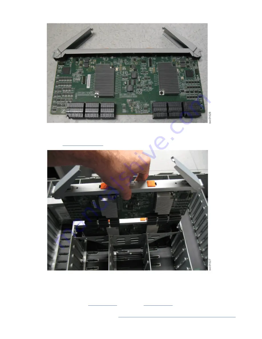
Figure 66. Open the secondary expander module handles

4. Align the edges of the secondary expander module carefully in the guide slot in the enclosure, as

shown in Figure 67 on page 65.

Figure 67. Replace the secondary expander module

5. Press the secondary expander module down into position in the enclosure.
6. Rotate the handles on the secondary expander module to the closed position to lock it in the

enclosure.

7. If needed, repeat step “3” on page 64 through step “6” on page 65 to replace the other secondary

expander module.

8. Replace the top cover, as described in “Installing or replacing the top cover: 2077-92F ” on page 58.

Chapter 2. Installing the system hardware  65

Summary of Contents for Storwize V5000 Gen 2 Series

Page 1: ...IBM Storwize V5000 Gen2 Quick Installation Guide IBM...

Page 2: ...v The information in the IBM Environmental Notices and User Guide provided on a DVD This edition applies to version 8 release 2 modification 1 and to all subsequent modifications until otherwise indic...

Page 3: ...er 2 Installing the system hardware 15 NEBS compliant earth connection 15 Installing support rails for 2U enclosures 15 Installing enclosures 19 Connecting expansion enclosures to the control enclosur...

Page 4: ...terface adapters 122 Connecting Ethernet cables to 25 Gbps iSCSI 2 port host interface adapters 122 Connecting Fibre Channel cables to a 10 Gbps iSCSI FCoE 4 port host interface adapter 123 Connecting...

Page 5: ...Index 149 v...

Page 6: ...vi...

Page 7: ...8 9 Enclosure support rails 9 10 DC power supply unit connectors and indicators 11 11 Enclosure support rails 16 12 Installing the rail spring 17 13 Hole locations in the front of the rack 17 14 Open...

Page 8: ...5 Attaching the inner rail section to the enclosure 45 36 Installing the rail assembly to the rack frame 46 37 Example of the required rack space 46 38 Example installation of the enclosure in the rac...

Page 9: ...top cover 58 57 Replacing the 2077 92F top cover 59 58 Locking the top cover 59 59 Drive assembly 60 60 Drive locations in a 5U expansion enclosure 60 61 Correct drive installation 61 62 Incorrect dr...

Page 10: ...to the drive board 78 84 Replace the FIB cover 78 85 Removing the 2077 92F enclosure from the rack 84 86 Releasing the power supply handles 85 87 Removed power supply 86 88 Drive assembly 87 89 Drive...

Page 11: ...e the rail assembly from the rear frame bracket 105 112 SAS cable connector orientation 106 113 Connecting the SAS cables 107 114 SAS port orientation on expansion enclosures 108 115 Features on the f...

Page 12: ...oE 4 port host interface adapters 124 132 Example Storwize V5020 configuration with 10 Gbps iSCSI FCoE 4 port host interface adapters 124 133 Example Storwize V5030 configuration with 10 Gbps iSCSI FC...

Page 13: ...current power replaceable units 13 11 Selecting bracket pins for your rack 18 12 Summary of SAS chains and enclosures 21 13 Weight of expansion enclosure parts 31 14 Weight of expansion enclosure dri...

Page 14: ...AS port LEDs 117 25 Supported expansion enclosure SAS drives 118 26 Storwize V5000 Gen2 system and warranty summary 119 27 Other expansion enclosure parts 119 28 Default user name and password for the...

Page 15: ...ebsite a Go to www ibm com support b Search for Storwize V5000 Gen2 c Click the documentation link Safety notices and labels Review the safety notices and safety information labels before you use this...

Page 16: ...d that has the potential of causing death or serious personal injury D002 CAUTION A caution notice indicates the presence of a hazard that has the potential of causing moderate or minor personal injur...

Page 17: ...bilizer brake function before each use Do not over force moving or rolling the LIFT TOOL with stabilizer brake engaged Do not raise lower or slide platform load shelf unless stabilizer brake pedal jac...

Page 18: ...e and may cause serious injury C048 part 2 of 2 CAUTION Removing components from the upper positions in the rack cabinet improves rack stability during a relocation Follow these general guidelines whe...

Page 19: ...ng an electrical storm The product might be equipped with multiple power cords To remove all hazardous voltages disconnect all power cords Connect all power cords to a properly wired and grounded elec...

Page 20: ...l PROTECTIVE EARTHING CONDUCTORS should terminate at this main protective earthing terminal or at points marked with R010 Special caution and safety notices This information describes special safety n...

Page 21: ...thers can handle and possibly damage the device While the device is still in its antistatic bag touch it to an unpainted metal part of the system unit for at least 2 seconds This action removes static...

Page 22: ...h and other languages The IBM Systems Environmental Notices includes statements on limitations product information product recycling and disposal battery information flat panel display refrigeration a...

Page 23: ...procedures as listed Be sure to gather IP addresses that you will need before you begin the installation Publications and related libraries Product manuals other publications and websites that contain...

Page 24: ...M Storwize V5100 IBM FlashSystem 5000 IBM FlashSystem 5100 IBM FlashSystem V9000 and IBM FlashSystem 9100 The guide describes the commands that you can use from the Storwize V5000 Gen 2 command line i...

Page 25: ...depending on the nature of your problem If you call from somewhere other than the US or Canada you must choose the hardware option when you call for assistance When you call IBM to service the produc...

Page 26: ...or software IBM maintains pages on the web where you can get the latest technical information and download device drivers and updates To access this information go to www ibm com support and follow th...

Page 27: ...rol enclosure only Control enclosure and one or more expansion enclosures Adding expansion enclosures Adding a control enclosure and expansion enclosures Storwize V5030 only Reviewing your packing sli...

Page 28: ...the system on page 131 Powering on the system on page 127 Powering on the system on page 127 Chapter 3 Configuring the system on page 131 Adding a control enclosure to an existing Storwize V5030 syste...

Page 29: ...structural damage Disconnect the attached power cords telecommunications systems networks and modems before you open the device covers unless instructed otherwise in the installation and configuratio...

Page 30: ...2078 124 24 slot Control enclosure for 2 5 inch drives IBM Storwize V5020 1 year 2077 212 12 slot Control enclosure for 3 5 inch drives 2077 224 24 slot Control enclosure for 2 5 inch drives 3 years 2...

Page 31: ...odules 3 years 2078 AFF 24 slot expansion enclosure for 2 5 inch flash drives 2078 A9F 92 slot expansion enclosure for flash drives and two secondary expander modules __ Rack mounting hardware kit __...

Page 32: ...entify the hardware components and port locations for the control enclosure and expansion enclosure on the system Control enclosure components The following figures show the rear view of the Storwize...

Page 33: ...he Storwize V5010 control enclosure Figure 5 on page 7 shows the data ports on the back of the Storwize V5020 control enclosure Figure 5 Data ports on the rear of the Storwize V5020 control enclosure...

Page 34: ...a 2U expansion canister Support rails and enclosures Storwize V5000 Gen2 systems use the same rails and enclosures for both control and expansion enclosures All Storwize V5000 Gen2 models use the same...

Page 35: ...y with the IBM provided power cord Do not use the IBM provided power cord for any other product Do not open or service any power supply assembly Do not connect or disconnect any cables or perform inst...

Page 36: ...he electrical current supplied to the device The device also might have more than one connection to DC power To remove all electrical current from the device ensure that all connections to DC power ar...

Page 37: ...that cool the enclosure Cool air is drawn in through the front of the enclosure The air passes over the drives node canisters and power supplies The warmed air is ejected through the rear of each powe...

Page 38: ...second 36 75 Inrush current at initial turn on 48V DC 34 A Out of spec time before power off is signaled 5 ms Important Each PSU cable must be protected by a 20A circuit breaker These instructions ass...

Page 39: ...ble You must also ensure that the requirements for power and environmental conditions are met This guide assumes that you have completed the physical planning for the environment of your system If you...

Page 40: ...f a rack is to be only partially filled install the enclosures low enough for the rack to remain stable and enable easy access to the enclosures for servicing Adding an expansion enclosure chain to an...

Page 41: ...it must be removed and the metal must be brought to a bright non corroding finish Upright mounting rails must have their own NEBS compliant connection to earth independent of the earth connections pr...

Page 42: ...l a Push one looped end of a spring over one stud on the inside of the rail See Figure 12 on page 17 b Stretch the spring slightly and push the other looped end of the spring onto the other stud on th...

Page 43: ...rt rails Figure 13 on page 17 shows two rack units with the front mounting holes identified Figure 13 Hole locations in the front of the rack 1 Upper rail mounting bracket pin 2 Lower rail mounting br...

Page 44: ...the medium pins and replace with the large pins supplied with the rails 5 At each end of the rail grasp the tab and pull firmly to open the hinge bracket as shown in Figure 14 on page 18 Figure 14 Op...

Page 45: ...nstall the control enclosure and optionally one or more expansion enclosures About this task Note For NEBS compliant installations more requirements are placed on the rack into which the support rails...

Page 46: ...Secure the enclosure with a screw in the rack mounting screw hole 5 Reinstall the left and right end caps See Figure 17 on page 20 The left end cap has indicator windows that align with the status LE...

Page 47: ...onnected together sequentially through the IN and OUT SAS ports forming a chain with a control enclosure at the end of the chain Note When connecting SAS cables between enclosures you must follow a li...

Page 48: ...on a Storwize V5020 system Figure 19 Connecting the SAS cables to a Storwize V5020 system Figure 20 on page 23 shows how to connect SAS cables on a Storwize V5030 or Storwize V5030F system In this fig...

Page 49: ...ansion chain a Connect SAS port 2 of the left node canister in the control enclosure to SAS port 1 of the left expansion canister in the second expansion enclosure b Connect SAS port 2 of the right no...

Page 50: ...nnector is probably oriented the wrong way Do not force it When inserted correctly the connector can only be removed by pulling the tab When both ends of a SAS cable are inserted correctly the green l...

Page 51: ...rom the shipping container 3 Install the enclosure in the rack by using the provided support rails 4 Install the fascia 5 Install the drives 6 Install the cable management arm 7 Connect the SAS expans...

Page 52: ...optional devices starting from the bottom of the rack cabinet Rack mounted devices are not to be used as shelves or work spaces Do not place objects on top of rack mounted devices Each rack cabinet mi...

Page 53: ...figuration of the rack cabinet as you received it If this configuration is not known you must observe the following precautions Remove all devices in the 32U position and above Ensure that the heavies...

Page 54: ...ducting wire used and the considered rating of the breaker The intent is to ensure the frame is electrically bonded to the PROTECTIVE EARTHING CONDUCTORS The hole that the bolt or stud goes into where...

Page 55: ...izer brake function before each use Do not over force moving or rolling the LIFT TOOL with stabilizer brake engaged Do not raise lower or slide platform load shelf unless stabilizer brake pedal jack i...

Page 56: ...C048 part 2 of 2 CAUTION If the System slide rails are installed above EIA location 29U the ServerLIFT tool or other qualified lift tool must be used as a safety precaution for servicing Position the...

Page 57: ...nt fascia 4U front cover 0 303 0 668 1 0 303 0 668 Display panel assembly 0 020 0 044 1 0 020 0 044 PSU fascia 1U cover 0 010 0 022 1 0 010 0 022 Power supply unit PSU 3 335 7 352 2 6 670 14 705 Secon...

Page 58: ...e 01LJ043 For systems with a 1 year warranty 2077 xxx 0 224 0 494 1 6 TB 2 5 inch tier 0 flash drive For systems with a 3 year warranty 2078 xxx 0 224 0 494 3 2 TB 2 5 inch tier 0 flash drive 01LJ044...

Page 59: ...System model 1 year warranty 3 year warranty Storwize V5010 2077 124 2078 124 Storwize V5020 2077 224 2078 224 Storwize V5030 2077 324 2078 324 Storwize V5030F 2077 AF3 2077 AF3 Weight increases as FR...

Page 60: ...terface board Display assembly Drives Cover 42 5 93 7 Enclosure 01LJ607 or 01LJ112 Secondary expansion modules Fascia 1U and 4U PSUs Expansion canisters Fan modules Fan interface board Display assembl...

Page 61: ...nisters Fan modules Fan interface board Display assembly Cover Fascia 1U and 4U Drives 61 5 135 4 Enclosure 01LJ607 or 01LJ112 Secondary expansion modules Fascia 1U and 4U PSUs Expansion canisters Fan...

Page 62: ...on the number of parts that remain you might need four persons or a mechanical lift to support the weight of the expansion enclosure Identify the hardware components 2077 92F You should become famili...

Page 63: ...e 23 Front fascia of the 2077 92F expansion enclosure Components on the rear of the enclosure Figure 24 on page 37 shows the components on the rear of the 2077 92F expansion enclosure Four fan modules...

Page 64: ...he support rails for the expansion enclosure The support rails are packaged separately from the expansion enclosure Figure 25 2077 92F support rails Cable management arm The cable management arm CMA w...

Page 65: ...unit remove all appropriate subassemblies per instructions to reduce the system weight C012 Important Before you unpack move install or service the 2077 92F expansion enclosure and its parts always c...

Page 66: ...talled in the enclosure However due to weight considerations you must remove some parts and then reinstall them as part of the initial installation process Note Drives are not included in installation...

Page 67: ...h 5 on page 45 in Installing or replacing the support rails 2077 92F on page 43 8 Attach the remaining sections of the support rails to the rack as described in step 6 on page 45 in Installing or repl...

Page 68: ...enclosure in a rack 2077 92F on page 47 17 Remove the cable management arm assembly from its packaging 2 in Figure 27 on page 40 18 Attach the cable management arm as described in Installing or replac...

Page 69: ...Replace the cover 5 To reinstall the cover or replace it with one from FRU stock follow the procedure in Installing or replacing the top cover 2077 92F on page 58 Installing or replacing the support...

Page 70: ...hen all components and drives are installed the expansion enclosure is heavy Install the support rails and enclosure at the lowest available position Do not install the rails and enclosure above posit...

Page 71: ...rail onto each side of the expansion enclosure as shown in Figure 35 on page 45 Figure 35 Attaching the inner rail section to the enclosure 6 Use the M5 screws to install the outer rail member and bra...

Page 72: ...the rail assembly to the rack frame For example Figure 37 on page 46 shows the front of the rail that is attached to the frame Figure 37 Example of the required rack space 46 Storwize V5000 Gen2 Quic...

Page 73: ...ime or replace it in the rack to complete a service task review and implement the following tasks Always use a suitably rated mechanical lift or four persons to raise the enclosure to install it in th...

Page 74: ...er in a 2077 92F expansion enclosure or replace a faulty expansion canister with one from FRU stock Before you begin Important You can replace an expansion canister without powering off the expansion...

Page 75: ...y align the expansion canister with the expansion enclosure 3 Rotate both the handles outward and insert the expansion canister into the expansion enclosure 4 When the expansion canister is fully inse...

Page 76: ...ment arms To complete many service tasks you can swing the CMA assemblies away from the expansion enclosure You do not have to completely remove the CMA assemblies from the enclosure For these service...

Page 77: ...or of the upper CMA assembly 3 in Figure 43 on page 51 4 Remove the outer connector from the inner member of the left support rail 4 in Figure 43 on page 51 5 Remove the inner connector of the upper C...

Page 78: ...of the right support rail 8 as shown in Figure 44 on page 52 Replace the CMA assembly 9 To reinstall the CMA or replace it with one from FRU stock follow the procedure in Installing or replacing the c...

Page 79: ...s swung away from the rear of the enclosure so that the expansion canister is accessible Figure 46 Lower CMA assembly moved Procedure 1 To release the upper CMA push the latch on the support rail conn...

Page 80: ...he lower CMA to the rail reverse the procedure Installing or replacing the cable management arm 2077 92F Use these procedures to install the cable management arm CMA for the 2077 92F expansion enclosu...

Page 81: ...ail hooks at the end of the support rails Figure 50 Upper and lower cable management arms Procedure 1 Remove the loop straps from the upper and lower CMA assemblies The straps are used only for shippi...

Page 82: ...ctor of the upper CMA assembly 1 to the inner member of the left support rail 2 as shown in Figure 52 on page 56 Figure 52 Install the inner connector of the upper CMA to the inner member of the suppo...

Page 83: ...rison Figure 55 on page 57 shows the upper and lower CMA assemblies as they are aligned to the support rails The support rail connector of the upper CMA attaches to the right rail The support rail con...

Page 84: ...ce the top cover on a 2077 92F expansion enclosure during the installation process or after you complete a service task Before you begin Important You can install the cover while the expansion enclosu...

Page 85: ...losure However to maintain operating temperature do not keep the cover off an operational enclosure for more than 15 minutes The reduction in airflow through the enclosure might cause the enclosure or...

Page 86: ...so by a fix procedure A label on the enclosure cover Figure 60 on page 60 shows the drive locations in the enclosure The drive slots are numbered 1 14 from left to right and A G from the back to the f...

Page 87: ...ted metal surface on the enclosure Wear an anti static wrist strap to remove the drive from the package 5 Ensure that the drive handle 1 in Figure 63 on page 62 of the drive assembly is in the open un...

Page 88: ...62 9 Ensure the toe on the bottom of the latch is fully engaged with the partition in the chassis 10 Ensure that the top toe of the latch is also fully engaged 4 in Figure 63 on page 62 11 Repeat ste...

Page 89: ...er of the enclosure is 01LJ607 you can remove or replace the secondary expander module while the enclosure is powered on Important You can replace a secondary expander module without powering off the...

Page 90: ...der module was removed as described in Removing a secondary expander module 2077 92F on page 89 Procedure 1 Slide the expansion enclosure out from the rack as described in Removing an expansion enclos...

Page 91: ...5 Press the secondary expander module down into position in the enclosure 6 Rotate the handles on the secondary expander module to the closed position to lock it in the enclosure 7 If needed repeat st...

Page 92: ...e power supply units PSUs on the enclosure As Figure 68 on page 66 shows the fascias are independent you can remove or replace one without having to remove or replace the other Figure 68 Fascia compon...

Page 93: ...or replacing a power supply 2077 92F Use the following procedures to replace either of the redundant power supplies in the 2077 92F expansion enclosure The redundant power supplies operate in parallel...

Page 94: ...enclosure as described in Removing the fascia 2077 92F on page 70 You are aware of the procedures for handling static sensitive devices Procedure 1 Read all safety information 2 Rotate the handles on...

Page 95: ...on the PSU and ensure the handle lock clicks in to place 5 Verify that the AC input and the DC power indicators are lit on the front of the PSU as shown in Figure 72 on page 69 Figure 72 Power supply...

Page 96: ...gure 73 on page 70 shows the fascias are independent you can remove or replace one without having to remove or replace the other Figure 73 Fascia components on the expansion enclosure Procedure 1 Use...

Page 97: ...move it from the chassis as shown in Figure 74 on page 71 The PSU fascia disengages from the slot and pin that connect it to each side of the chassis You must remove the bottom fascia to access and se...

Page 98: ...remove If you replace more than one cable record which two ports canisters and enclosures each cable connects so you can match the connections with the replacement cables The system cannot operate if...

Page 99: ...the cable is successfully inserted you cannot disconnect the cable without pulling on the blue tag Connecting to a Storwize V5000 Gen 2 node 7 Connect the SAS cable to the SAS port with blue tab abov...

Page 100: ...xt to the connected SAS ports are lit For example Figure 78 on page 74 shows the LEDs of expansion canister 1 on a 2077 92F expansion enclosure The SAS cable is successfully inserted in to port 1 inpu...

Page 101: ...About this task The expansion enclosure might or might not be powered on depending on the number of fan modules that need to be replaced For example the expansion enclosure must be powered off if all...

Page 102: ...page 79 A lift is supporting the weight of the enclosure The top cover fans drives and other heavy FRUs are removed from the enclosure About this task The 2077 92F expansion enclosure contains two fa...

Page 103: ...nsion enclosure chassis as shown in Figure 82 on page 77 Figure 82 Insert the new FIB in the chassis 3 Use a cross head screwdriver to tighten the retaining screws that secure the FIB to the drive boa...

Page 104: ...e 77 and 3 on page 77 to replace the other FIB 5 Replace the narrow metal cover which is shown in Figure 84 on page 78 over the FIB assemblies The attachment screws are on each side of the chassis Fig...

Page 105: ...xpansion enclosure 2077 92F on page 108 Removing an expansion enclosure from a rack 2077 92F You might need to slide the 2077 92F expansion enclosure out of the rack to apply service For some tasks yo...

Page 106: ...should be given to the connection of the equipment to the supply circuit so that overloading of the circuits does not compromise the supply wiring or overcurrent protection To provide the correct pow...

Page 107: ...f the pallet and bolt the rack cabinet to the pallet R002 DANGER Racks with a total weight of 227 kg 500 lb Use Only Professional Movers R003 DANGER Do not transport the rack via fork truck unless it...

Page 108: ...t Local paper manual must remain with machine in provided storage sleeve area Latest revision manual available on vendor s website Test verify stabilizer brake function before each use Do not over for...

Page 109: ...heard as the equipment is being raised Be sure winch is locked in position before releasing handle Read instruction page before operating this winch Never allow winch to unwind freely Freewheeling wi...

Page 110: ...cedure step 5 on page 84 through step 7 on page 84 only if you must completely remove the expansion enclosure from the rack to complete a service procedure 5 Power down the expansion enclosure and dis...

Page 111: ...t cause the enclosure or its components to shut down to protect from overheating About this task Each PSU provides cooling to the lower part of the enclosure Ensure that the second PSU in the enclosur...

Page 112: ...in Installing or replacing a power supply 2077 92F on page 67 Removing a drive 2077 92F You can remove a faulty drive from a 2077 92F expansion enclosure to replace it with a new one received from FRU...

Page 113: ...ck as described in Removing an expansion enclosure from a rack 2077 92F on page 79 3 Remove the top cover as described in Removing the top cover 2077 92F on page 42 4 Locate the slot that contains the...

Page 114: ...le 2 to unlock the drive carrier from the partition as shown in Figure 90 on page 88 Ensure the toe on the bottom of the latch is fully disengaged 7 Carefully lift the drive carrier up to remove it fr...

Page 115: ...r module without powering off the expansion enclosure However to maintain operating temperature perform the following tasks Do not remove a faulty secondary expander module until its replacement is re...

Page 116: ...e LEDs identify the operational status of the secondary expander modules Figure 92 Location of LEDs on the secondary expander module Table 18 on page 90 describes the function and status values of eac...

Page 117: ...r 2077 92F on page 42 Procedure 1 Identify the secondary expander module to be replaced refer to Table 18 on page 90 2 Press the release buttons on top of the secondary expander module to release the...

Page 118: ...ansion module 7 To reinstall the secondary expansion module or replace it with one from FRU stock follow the procedure in Installing or replacing a secondary expander module 2077 92F on page 63 Removi...

Page 119: ...the full I O load Figure 96 on page 93 shows the features of an expansion enclosure Figure 96 Expansion canister 1 Canister fault indicator 2 Canister status 3 Canister power indicator 4 and 6 SAS lin...

Page 120: ...enclosure However to maintain operating temperature do not remove more than one fan module at a time Remove a faulty fan module only when its replacement is ready to be installed Do not remove a fan...

Page 121: ...e status of the fan modules 2 Press the release tab on the fan module as Figure 99 on page 95 shows Figure 99 Fan module release tab 3 Use the handle to pull the fan module out of the expansion enclos...

Page 122: ...ved from the rack as described in Removing an expansion enclosure from a rack 2077 92F on page 79 Ensure that you use a lift to support the weight of the enclosure About this task The 2077 92F expansi...

Page 123: ...s as shown in Figure 102 on page 97 The screws are on each side of the chassis Place the cover and cover screws in a safe location Figure 102 Location of the FIB cover 2 Use a cross head screwdriver t...

Page 124: ...e to pull the FIB out of the expansion enclosure chassis as shown in Figure 104 on page 98 Figure 104 Remove the FIB from the chassis 4 Place the FIB shown in Figure 105 on page 99 in a safe location...

Page 125: ...nclosure 2077 92F You can replace a faulty enclosure of a 2077 92F expansion enclosure with a new one from FRU stock Before you begin DANGER Multiple power cords The product might be equipped with mul...

Page 126: ...bly rated mechanical lift is available to support the weight of the enclosure About this task The expansion enclosure contains the drive board signal interconnect board and internal power cables If a...

Page 127: ...58 8 Reconnect the SAS cables as described in Removing and installing a SAS cable 2077 92F on page 72 9 Reconnect the power cables as described in Powering on the 5U expansion enclosure 2077 92F on pa...

Page 128: ...isplay panel assembly 5 To reinstall the display panel assembly or replace it with one from FRU stock follow the procedure in Installing or replacing the display panel assembly 2077 92F on page 103 10...

Page 129: ...he rack on the slide rails as described in Removing an expansion enclosure from a rack 2077 92F on page 79 The top cover was removed as described in Removing the top cover 2077 92F on page 42 The disp...

Page 130: ...anel assembly in the slot at the front of the expansion enclosure as shown in Figure 109 on page 105 Ensure the display panel assembly which is shown in Figure 108 on page 104 faces toward the outside...

Page 131: ...removed as described in Removing or moving the cable management arm 2077 92F or 2078 92F on page 50 The expansion enclosure is removed from the rack as described in Removing an expansion enclosure fr...

Page 132: ...the connector can be removed only by pulling the tab Be aware of the following guidelines when you attach the cables to the SAS ports No cable can be connected between a port on a left canister and a...

Page 133: ...um number of I O groups that is supported depends on the model of your system Two chains of expansion enclosures can be attached to each I O group On each SAS chain the systems can support up to a SAS...

Page 134: ...ntation of the Input and Output SAS ports on the 2U and 5U SAS enclosures differs Figure 114 on page 108 shows the SAS ports on the 2077 92F 2077 2078 12F and 2077 2078 24F expansion enclosures Figure...

Page 135: ...the 2077 92F expansion enclosure 1 Display panel LEDs 2 Rack retention thumb screws 3 Power supply unit LEDs 4 Power supply units PSUs 5 PSU fascia 1U 6 Front fascia 4U Each PSU has a power supply co...

Page 136: ...e the expansion enclosure out of the rack to perform service tasks Figure 117 Power and SAS cable connections on the back of the enclosure 3 Verify that the expansion enclosure and its components are...

Page 137: ...cted You can also access the Event Log to view enclosure and component events and complete any remaining fix procedures Powering off the expansion enclosure 2077 92F Before you power down a 2077 92F e...

Page 138: ...y expander module Note All of the information about the 2077 92F expansion enclosure is also applicable to the 2077 A9F 2078 A9F and 2078 92F expansion enclosures LEDs on the front of the expansion en...

Page 139: ...ff No faults are detected The 2077 92F expansion enclosure contains two PSUs 4 in Figure 119 on page 112 that are accessible from the front of the enclosure Each PSU has its own a set of LEDs as shown...

Page 140: ...on enclosure has two LED indicators Figure 121 on page 114 shows the components of a drive assembly Each drive has an online indicator 2 and fault indicator 3 Figure 121 LEDs on a drive assembly Table...

Page 141: ...122 LEDs on a secondary expansion module 1 Online indicator 2 Fault indicator Table 23 on page 115 describes the meaning of the LEDs on each secondary expansion module Table 23 LED indicators on secon...

Page 142: ...ting normally the LED is not lit If a fault is detected the amber LED is lit As Figure 123 on page 116 also shows the expansion enclosure contains two expansion canisters Each expansion canister conta...

Page 143: ...ons are possible Only 1 2 or 3 phys are connected but not all 4 The phys are not operating at the same speed All phys are not connected to the same remote port One or more of the connected lanes are a...

Page 144: ...For systems with a 3 year warranty 2078 xxx 3 2 TB tier 0 flash drive 01LJ044 For systems with a 1 year warranty 2077 xxx For systems with a 3 year warranty 2078 xxx 1 92 TB tier 1 flash drive 01LJ045...

Page 145: ...U The expansion enclosure contains 2 PSUs Each PSU requires a C19 C20 power cord 01LJ124 use with enclosure FRU P N 01LJ112 01LJ860 use with enclosure FRU P N 01LJ607 Secondary expansion module The ex...

Page 146: ...e green cable Port 2 serves as the technician port when the system is initially set up or when service is needed In the figures port 2 is identified by the blue cable After the system initializes port...

Page 147: ...port is identified by the green cable Note Never use the technician port to provide an Ethernet connection to the system Do not connect the Ethernet technician port to a network switch The technician...

Page 148: ...ft canister and the right canister 2 Connect the appropriate cable to each port 3 For each additional pair of Ethernet ports in the right and left canisters identify the correct pair of cables and con...

Page 149: ...rnet ports in the right and left canisters identify the correct pair of cables and connect them Note The Ethernet cables are connected in pairs Both canisters must have the same number of cables conne...

Page 150: ...ost interface adapters Figure 133 Example Storwize V5030 configuration with 10 Gbps iSCSI FCoE 4 port host interface adapters Connecting Fibre Channel cables to a Fibre Channel adapter in the enclosur...

Page 151: ...zoning on the Fibre Channel switches Configure the network so that every node canister has at least two connections to every node canister in a different control enclosure You must configure the netwo...

Page 152: ...the connector can only be removed by pulling the tab Procedure To install the cables complete the following steps 1 Connect the required number of SAS cables Refer to the Planning section of the IBM K...

Page 153: ...ainers to secure the power cables from being accidentally pulled out of the enclosure The cable retainer which is on the back of each PSU handle has a curved opening that faces the rear of the PSU Aft...

Page 154: ...the system status using the LEDs topic in Troubleshooting 3 Wait for all expansion canisters to finish powering on 4 Power on the control enclosure Use the supplied power cords to connect both power s...

Page 155: ...l errors when Power is illuminated Status is flashing and Fault is off If a canister is not ready refer to the Procedure Understanding the system status using the LEDs topic in Troubleshooting Chapter...

Page 156: ...130 Storwize V5000 Gen2 Quick Installation Guide...

Page 157: ...ures These can be added by following the procedure in Adding an expansion enclosure to an existing system on page 136 Checking your web browser settings for the management GUI To access the management...

Page 158: ...b address was added to the Trusted sites window f Click Close on the Trusted sites window g Click OK h Refresh your browser For Google Chrome complete the following steps a On the menu bar in the Goog...

Page 159: ...ft Edge running on Microsoft Windows 10 file download is enabled by default and requires no additional configuration 4 Enable scripts to disable or replace context menus Mozilla Firefox only For Mozil...

Page 160: ...n Ethernet port on the personal computer to enable Dynamic Host Configuration Protocol DHCP configuration of its IP address and DNS settings If you do not have DHCP you must manually configure the per...

Page 161: ...between the personal computer and the technician port Configuring a system to be NEBS compliant For operation in Network Equipment Building System NEBS compliant installations the system can be config...

Page 162: ...elect Monitoring System On the System Overview page select Add Enclosure When a new enclosure is cabled correctly to the system the Add Enclosures action automatically displays on the System Overview...

Page 163: ...select Monitoring System On the System Overview page select Add Enclosure When a new enclosure is cabled correctly to the system the Add Enclosures action automatically displays on the System Overview...

Page 164: ...138 Storwize V5000 Gen2 Quick Installation Guide...

Page 165: ...d connectors The system online documentation and its related publications are accessibility enabled The accessibility features of the online documentation are described in Viewing information in the i...

Page 166: ...140 Storwize V5000 Gen2 Quick Installation Guide...

Page 167: ...d Warranty is available in both hardcopy format and in the Storwize V5000 IBM Knowledge Center The Statement of Limited Warranty is included in hardcopy form with your product See Publications and rel...

Page 168: ...142 Storwize V5000 Gen2 Quick Installation Guide...

Page 169: ...pan Ltd 19 21 Nihonbashi Hakozakicho Chuo ku Tokyo 103 8510 Japan INTERNATIONAL BUSINESS MACHINES CORPORATION PROVIDES THIS PUBLICATION AS IS WITHOUT WARRANTY OF ANY KIND EITHER EXPRESS OR IMPLIED INC...

Page 170: ...names and addresses used by an actual business enterprise is entirely coincidental COPYRIGHT LICENSE This information contains sample application programs in source language which illustrate programm...

Page 171: ...ant with Class A of CISPR 32 In a residential environment this equipment may cause radio interference Germany Notice Deutschsprachiger EU Hinweis Hinweis f r Ger te der Klasse A EU Richtlinie zur Elek...

Page 172: ...eutschland GmbH Technical Relations Europe Abteilung M456 IBM Allee 1 71139 Ehningen Germany Tel 49 800 225 5426 e mail Halloibm de ibm com Generelle Informationen Das Ger t erf llt die Schutzanforder...

Page 173: ...Japan Voluntary Control Council for Interference VCCI Notice Korea Notice People s Republic of China Notice Russia Notice Taiwan Notice Notices 147...

Page 174: ...y to cause harmful interference in which case the user will be required to correct the interference at his own expense Properly shielded and grounded cables and connectors must be used in order to mee...

Page 175: ...nits connecting to power source 12 replaceable units 13 DC power supply units connectors 11 LEDs 11 direct current power supply units connecting to power source 12 connectors 11 LEDs 11 replaceable un...

Page 176: ...v removing 2077 92F 2078 92F power supply 85 support rails 42 cable management arm 50 replacing 2077 92F 2078 92F top covers 58 5U expansion enclosure SAS cable 72 cable management arm 54 top cover 20...

Page 177: ......

Page 178: ...IBM...

Reviews: