


84
Upgrading
the
Hardware
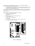
TP184
Carrier
Sidewall
Screw
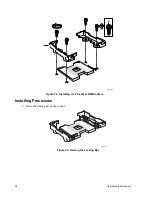
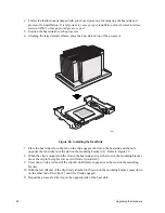
Figure 19. Floppy Driver Carrier Assembly
A. Floppy drive carrier metal housing
B. Floppy drive carrier interface board
C. Two screws to connect interface board to metal housing
D. Floppy Drive
One FFC cable is required to connect between the Floppy drive carrier interface board (B) and the
Floppy drive (D). This FFC cable has a keying feature that allows it to be inserted correctly in only
one orientation.
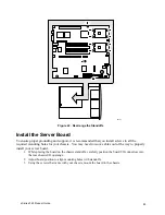
The Floppy drive carrier assembly inserts into the peripheral bay on the front of the system. The
mating connectors on the Floppy drive carrier assembly and the FPIO board are blind-mate, and will
seat fully when the horizontal handle on the Floppy drive carrier assembly is fully secured.
Working Inside the System
This section presents the following procedures that describe removal and installation of most
components inside the system.
Safety: Before You Remove Server Covers
Before removing covers at any time to work inside the system, observe these safety guidelines:
1.
Turn off all peripheral devices connected to the system.
2.
Power down the system by pressing and holding the Power button on the front of the chassis for
several seconds. After the server shuts down, unplug/disconnect the power cord to remove
standby power from the server.
3.
Label and disconnect all peripheral cables and all telecommunication lines connected to
I/O connectors or ports on the back of the system.
Provide ESD protection by wearing an anti-static wrist strap attached to chassis ground (any
unpainted metal surface) of the server when handling components.
Summary of Contents for @server xSeries 343
Page 1: ... TM xSeries 343 Product Guide ...
Page 3: ......
Page 4: ...ii ...
Page 12: ...x Contents This page intentionally left blank ...
Page 32: ...20 Chassis Description Must enter the administrator password to exit secure mode ...
Page 119: ...xSeries 343 Product Guide 107 TP00472 Figure 37 Removing the Power Supply Cage ...
Page 157: ...xSeries 343 Product Guide 145 ...
Page 158: ...146 Appendix C Safety Information ...
Page 159: ...xSeries 343 Product Guide 147 ...
Page 160: ...148 Appendix C Safety Information ...
Page 161: ...xSeries 343 Product Guide 149 ...
Page 162: ...150 Appendix C Safety Information ...
Page 163: ...xSeries 343 Product Guide 151 ...
Page 164: ...152 Appendix C Safety Information ...
Page 165: ...xSeries 343 Product Guide 153 ...
Page 166: ...154 Appendix C Safety Information ...
Page 167: ...xSeries 343 Product Guide 155 ...
Page 177: ...xSeries 343 Product Guide 165 ...
Page 178: ...166 Appendix C Safety Information ...
Page 179: ...xSeries 343 Product Guide 167 ...
Page 180: ...168 Appendix C Safety Information ...
Page 181: ...xSeries 343 Product Guide 169 ...
Page 182: ...170 Appendix C Safety Information ...
Page 183: ...xSeries 343 Product Guide 171 ...
Page 189: ...xSeries 343 Product Guide 177 ...
Page 193: ...xSeries 343 Product Guide 181 Part Number 24R9084 Printed in the United States of America ...


