


xSeries 343 Product Guide
13
Table 3.
Front Panel Features
Item Feature
Description
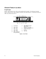
Front Panel Switches
A
Power switch
Toggles the system power
B
Reset switch
Resets the system
L
ID switch
Toggles system ID LED
M
NMI switch
Assert NMI to baseboard
Front Panel Alarm LEDs and Relays
C
Critical (amber or red)
When continuously lit, indicates the presence of a Critical System
Fault. A critical system fault is an error or event that is detected by the
system with a fatal impact to the system. In this case, the system
cannot continue to operate. An example could be the loss of a large
section of memory, or other corruption, that renders the system not
operational. The front panel critical alarm relay will be engaged.
D
Major (amber or red)
When continuously lit, indicates the presence of a Major System Fault.
A major system fault is an error or event that is detected by the system
that has discernable impact to system operation. In this case, the
system can continue to operate but in a “degraded” fashion (reduced
performance or loss of non-fatal feature reduction). An example could
be the loss of one of two mirrored disks. The front panel major alarm
relay will be engaged.
E
Minor (amber)
When continuously lit, indicates the presence of a Minor System Fault.
A minor system fault is an error or event that is detected by the system
but has little impact to actual system operation. An example would be
a correctable ECC error. The front panel minor alarm relay will be
engaged.
F
Power (amber)
When continuously lit, indicates the presence of a Power System
Fault. The front panel power alarm relay will be engaged.
Front Panel Status LEDs
G
Disk 1 Activity/Fault LED
(green/amber or red)
Indicates disk 1 SCSI hard drive activity when green, or a disk 1 SCSI
hard drive fault when amber or red.
H
Disk 2 Activity/Fault LED
(green/amber or red)
Indicates disk 2 SCSI hard drive activity when green, or a disk 2 SCSI
hard drive fault when amber or red.
I
Main power LED (green)
When continuously lit, indicates the presence of DC power in the
server. The LED goes out when the power is turned off or the power
source is disrupted.
J
NIC0/NIC1 activity LED (green)
Indicates activity on either NIC0 or NIC1.
K
System ID LED (white)
Indicates any system SCSI hard drive activity.
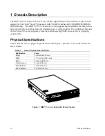
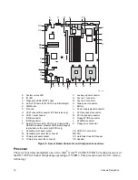
Figure 3 shows the front view of the system with the bezel removed.
Summary of Contents for @server xSeries 343
Page 1: ... TM xSeries 343 Product Guide ...
Page 3: ......
Page 4: ...ii ...
Page 12: ...x Contents This page intentionally left blank ...
Page 32: ...20 Chassis Description Must enter the administrator password to exit secure mode ...
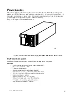
Page 119: ...xSeries 343 Product Guide 107 TP00472 Figure 37 Removing the Power Supply Cage ...
Page 157: ...xSeries 343 Product Guide 145 ...
Page 158: ...146 Appendix C Safety Information ...
Page 159: ...xSeries 343 Product Guide 147 ...
Page 160: ...148 Appendix C Safety Information ...
Page 161: ...xSeries 343 Product Guide 149 ...
Page 162: ...150 Appendix C Safety Information ...
Page 163: ...xSeries 343 Product Guide 151 ...
Page 164: ...152 Appendix C Safety Information ...
Page 165: ...xSeries 343 Product Guide 153 ...
Page 166: ...154 Appendix C Safety Information ...
Page 167: ...xSeries 343 Product Guide 155 ...
Page 177: ...xSeries 343 Product Guide 165 ...
Page 178: ...166 Appendix C Safety Information ...
Page 179: ...xSeries 343 Product Guide 167 ...
Page 180: ...168 Appendix C Safety Information ...
Page 181: ...xSeries 343 Product Guide 169 ...
Page 182: ...170 Appendix C Safety Information ...
Page 183: ...xSeries 343 Product Guide 171 ...
Page 189: ...xSeries 343 Product Guide 177 ...
Page 193: ...xSeries 343 Product Guide 181 Part Number 24R9084 Printed in the United States of America ...


