


xSeries 343 Product Guide
79
Hazardous conditions, devices and cables
:
Hazardous electrical
conditions may be present on power, telephone, and communication cables.
Turn off the server and disconnect the power cord, telecommunications
systems, networks, and modems attached to the server before opening it.
Otherwise, personal injury or equipment damage can result.
Electrostatic discharge (ESD) and ESD protection:
ESD can damage
disk drives, boards, and other parts. We recommend that you perform all
procedures in this chapter only at an ESD workstation. If one is not available,
provide some ESD protection by wearing an anti-static wrist strap attached to
chassis ground (any unpainted metal surface) on your server when handling
parts.
ESD and handling boards:
Always handle boards carefully. They can be
extremely sensitive to ESD. Hold boards only by their edges. After removing a
board from its protective wrapper or from the server, place the board component
side up on a grounded, static-free surface. Use a conductive foam pad if
available but not the board wrapper. Do not slide board over any surface.
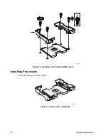
Replacing Power Supply Modules
✏
NOTE
To maintain hot plug capability, ensure that an active AC or DC Power Supply
Module is in the second Power Supply Module slot before replacing a Power
Supply Module.
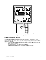
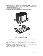
To replace an AC power supply module, follow this procedure:
1.
Press in locking tab inside of green handle (A in Figure 14).
2.
Pull green handle slightly downward and rearward, sliding AC Power Supply Module out of AC
Power Supply Cage (B and C in Figure 14).
3.
When reinserting AC Power Supply Module, make sure the green handle is in the downward
position before sliding AC Power Supply Module into AC Power Supply Cage.
To replace a DC power supply module, follow this procedure:
1.
Using a small flat-head screwdriver, unlatch the black connector cover from the connector base
and flip connector cover up (see D in Figure 14).
2.
Disconnect DC power plug from power supply module by pulling DC power plug rearward (see E
in Figure 14). Flip black connector cover down and re-latch connector cover to connector base.
3.
Press in green button on handle and pull handle downward. At the same time, pull DC Power
Supply Module out of DC Power Supply Cage (see F, G, and H in Figure 14).
4.
When reinserting DC Power Supply Module, make sure the handle is in the downward position
before sliding DC Power Supply Module into DC Power Supply Cage.
Summary of Contents for @server xSeries 343
Page 1: ... TM xSeries 343 Product Guide ...
Page 3: ......
Page 4: ...ii ...
Page 12: ...x Contents This page intentionally left blank ...
Page 32: ...20 Chassis Description Must enter the administrator password to exit secure mode ...
Page 119: ...xSeries 343 Product Guide 107 TP00472 Figure 37 Removing the Power Supply Cage ...
Page 157: ...xSeries 343 Product Guide 145 ...
Page 158: ...146 Appendix C Safety Information ...
Page 159: ...xSeries 343 Product Guide 147 ...
Page 160: ...148 Appendix C Safety Information ...
Page 161: ...xSeries 343 Product Guide 149 ...
Page 162: ...150 Appendix C Safety Information ...
Page 163: ...xSeries 343 Product Guide 151 ...
Page 164: ...152 Appendix C Safety Information ...
Page 165: ...xSeries 343 Product Guide 153 ...
Page 166: ...154 Appendix C Safety Information ...
Page 167: ...xSeries 343 Product Guide 155 ...
Page 177: ...xSeries 343 Product Guide 165 ...
Page 178: ...166 Appendix C Safety Information ...
Page 179: ...xSeries 343 Product Guide 167 ...
Page 180: ...168 Appendix C Safety Information ...
Page 181: ...xSeries 343 Product Guide 169 ...
Page 182: ...170 Appendix C Safety Information ...
Page 183: ...xSeries 343 Product Guide 171 ...
Page 189: ...xSeries 343 Product Guide 177 ...
Page 193: ...xSeries 343 Product Guide 181 Part Number 24R9084 Printed in the United States of America ...


