


18
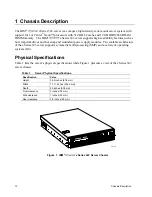
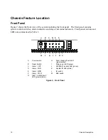
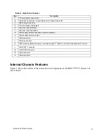
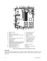
Chassis
Description
Network Controller
✏
NOTE
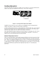
To ensure EMC product regulation compliance for intra-building lighting
surges, the system must only be used with shielded LAN cables that are
grounded at both ends.
The server board uses the Intel
®
Fast Ethernet Controller 82546EB and supports two
10Base-T/100Base-T/1000Base-TX network subsystems.
The 82546EB controller supports the following features:
•
32-bit PCI master interface
•
Integrated IEEE 802.3 10Base-T, 100Base-TX and 1000Base-TX compatible PHY
•
IEEE 820.3u auto-negotiation support
•
Full-duplex support at 10 Mbps, 100 Mbps, and 1000 Mbps operation
•
Low power +3.3 V device
On the server board, NIC 1 can be used as both a network interface and server management
interface.
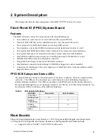
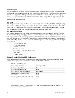
NIC Connector and Status LEDs
The E82546EB controller drives LEDs on the network interface connector that indicate
link/activity on the LAN and speed of operation. The green LED indicates network connection
when on and TX/RX activity when blinking. The speed LED indicates 1000 Mbps when amber,
100 Mbps when green, and 10 Mbps when off.
Keyboard and Mouse
The keyboard/mouse controller is PS/2-compatible. If specified through the System Setup Utility,
the server may be locked automatically if there is no keyboard or mouse activity for a predefined
length of time. Once the inactivity (lockout) timer has expired, the keyboard and mouse do not
respond until the previously stored password is entered. A Y-cable can be used if both a PS/2
mouse and keyboard are required at the same time.
RJ-45 Serial Port
The rear RJ-45 serial port is a fully functional serial port that supports any standard serial device
and provides support for serial concentrators. For server applications that use a serial concentrator
to access the server management features of the baseboard, a standard 8-pin CAT-5 cable from the
serial concentrator is plugged directly into the rear RJ-45 serial port. The 8 pins of the RJ-45
connector can be configured to match either of two pin-out standards used by serial port devices.
To accommodate either standard, the J5A2 jumper block located directly behind the rear RJ-45
serial port must be jumpered appropriately according to the desired standard.
✏
NOTE
By default, the RJ-45 serial port is configured to support a DSR signal.
Summary of Contents for @server xSeries 343
Page 1: ... TM xSeries 343 Product Guide ...
Page 3: ......
Page 4: ...ii ...
Page 12: ...x Contents This page intentionally left blank ...
Page 32: ...20 Chassis Description Must enter the administrator password to exit secure mode ...
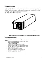
Page 119: ...xSeries 343 Product Guide 107 TP00472 Figure 37 Removing the Power Supply Cage ...
Page 157: ...xSeries 343 Product Guide 145 ...
Page 158: ...146 Appendix C Safety Information ...
Page 159: ...xSeries 343 Product Guide 147 ...
Page 160: ...148 Appendix C Safety Information ...
Page 161: ...xSeries 343 Product Guide 149 ...
Page 162: ...150 Appendix C Safety Information ...
Page 163: ...xSeries 343 Product Guide 151 ...
Page 164: ...152 Appendix C Safety Information ...
Page 165: ...xSeries 343 Product Guide 153 ...
Page 166: ...154 Appendix C Safety Information ...
Page 167: ...xSeries 343 Product Guide 155 ...
Page 177: ...xSeries 343 Product Guide 165 ...
Page 178: ...166 Appendix C Safety Information ...
Page 179: ...xSeries 343 Product Guide 167 ...
Page 180: ...168 Appendix C Safety Information ...
Page 181: ...xSeries 343 Product Guide 169 ...
Page 182: ...170 Appendix C Safety Information ...
Page 183: ...xSeries 343 Product Guide 171 ...
Page 189: ...xSeries 343 Product Guide 177 ...
Page 193: ...xSeries 343 Product Guide 181 Part Number 24R9084 Printed in the United States of America ...


