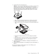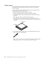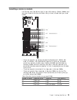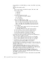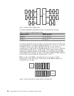
The following table lists the installation sequence for installing DIMMs in
memory-mirroring mode.
Table 12. Memory-mirroring mode DIMM population sequence
DIMMs
Number of installed
microprocessors
DIMM connector
First pair of DIMMs
1
3, 6
Second pair of DIMMs
1
2, 5
Third pair of DIMMs
1
1, 4
Fourth pair of DIMMs
2
14, 11
Fifth pair of DIMMs
2
13, 10
Sixth pair of DIMMs
2
12, 9
Note:
DIMM connectors 7, 8, 15, and 16 are not used in memory-mirroring mode.
When you install or remove DIMMs, the server configuration information changes.
When you restart the server, the system displays a message that indicates that the
memory configuration has changed.
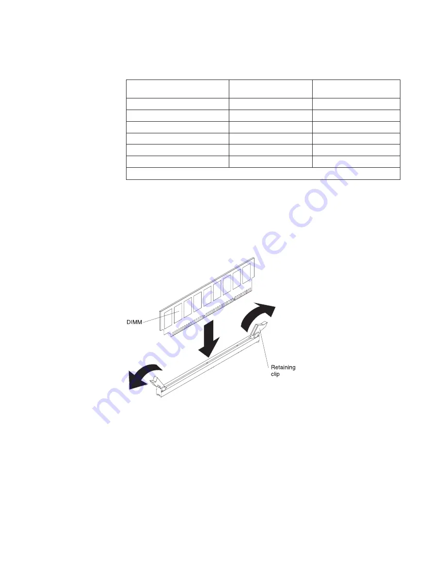
Installing a DIMM
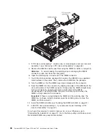
To install a DIMM, complete the following steps.
1. Read the safety information that begins on page vii and “Installation guidelines”
on page 38.
2. Turn off the server and peripheral devices, and disconnect the power cord and
all external cables (see “Turning off the server” on page 22).
3. Remove the server cover (see “Removing the cover” on page 44).
Chapter 2. Installing optional devices
87
Summary of Contents for 7947E3U
Page 1: ......
Page 2: ......
Page 3: ...System x3650 M2 Types 4199 and 7947 Installation and User s Guide...
Page 8: ...vi System x3650 M2 Types 4199 and 7947 Installation and User s Guide...
Page 16: ...xiv System x3650 M2 Types 4199 and 7947 Installation and User s Guide...
Page 40: ...24 System x3650 M2 Types 4199 and 7947 Installation and User s Guide...
Page 150: ...134 System x3650 M2 Types 4199 and 7947 Installation and User s Guide...
Page 168: ...152 System x3650 M2 Types 4199 and 7947 Installation and User s Guide...
Page 169: ......
Page 170: ...Part Number 81Y6111 Printed in USA 1P P N 81Y6111...

