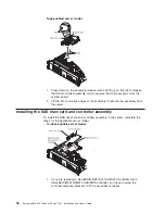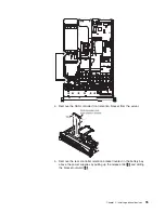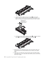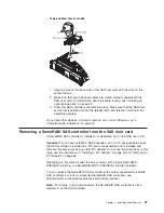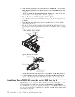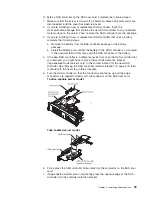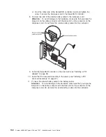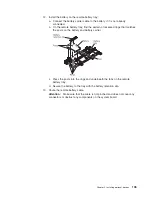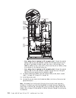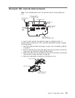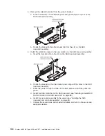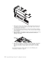
8. Install the SAS riser-card and controller assembly (see “Installing the SAS
riser-card and controller assembly” on page 94).
If you have other devices to install or remove, do so now. Otherwise, go to
“Completing the installation” on page 111.
Notes:
1. When you restart the server for the first time after you install a SAS controller
with a battery, the monitor screen remains blank while the controller initializes
the battery. This might take a few minutes, after which the startup process
continues. This is a one-time occurrence.
Important:
You must allow the initialization process to be completed. If you do
not, the battery pack will not work, and the server might not start.
The battery comes partially charged, at 30% or less of capacity. Run the server
for 4 to 6 hours to fully charge the controller battery. The LED just above the
battery on the controller remains lit until the battery is fully charged.
Until the battery is fully charged, the controller firmware sets the controller
cache to write-through mode; after the battery is fully charged, the controller
firmware re-enables write-back mode.
2. When you restart the server, you are given the opportunity to import the existing
RAID configuration to the new ServeRAID SAS controller.
Installing a ServeRAID SAS controller battery on the remote battery
tray
The Intelligent Battery Backup Unit (iBBU) is an optional battery for the
ServeRAID-MR10i SAS/SATA controller and a standard battery for the
ServeRAID-MR10M SAS/SATA controller. It is referred to as the
battery
throughout
this section.
When you install a ServeRAID SAS controller in a PCI riser-card assembly in the
server, you must install the battery at a distance from the ServeRAID controller to
avoid overheating. This section describes the process for installing a battery or
batteries in the server.
To install a battery, complete the following steps:
1. Read the safety information that begins on page vii and “Installation guidelines”
on page 38.
2. Turn off the server and peripheral devices and disconnect all power cords and
external cables (see “Turning off the server” on page 22).
3. Remove the cover (see “Removing the cover” on page 44).
4. Remove the PCI riser-card assembly from the server and set it aside (see
“Removing a PCI riser-card assembly” on page 46).
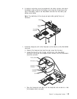
5. Remove the ServeRAID controller from the riser card (see “Removing a PCI
adapter” on page 56).
100
System x3650 M2 Types 4199 and 7947: Installation and User’s Guide
Summary of Contents for 7947E3U
Page 1: ......
Page 2: ......
Page 3: ...System x3650 M2 Types 4199 and 7947 Installation and User s Guide...
Page 8: ...vi System x3650 M2 Types 4199 and 7947 Installation and User s Guide...
Page 16: ...xiv System x3650 M2 Types 4199 and 7947 Installation and User s Guide...
Page 40: ...24 System x3650 M2 Types 4199 and 7947 Installation and User s Guide...
Page 150: ...134 System x3650 M2 Types 4199 and 7947 Installation and User s Guide...
Page 168: ...152 System x3650 M2 Types 4199 and 7947 Installation and User s Guide...
Page 169: ......
Page 170: ...Part Number 81Y6111 Printed in USA 1P P N 81Y6111...

