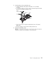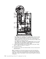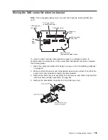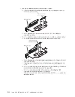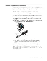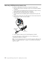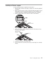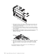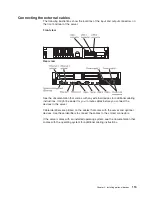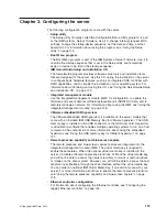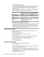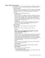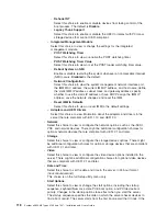
Connecting the external cables
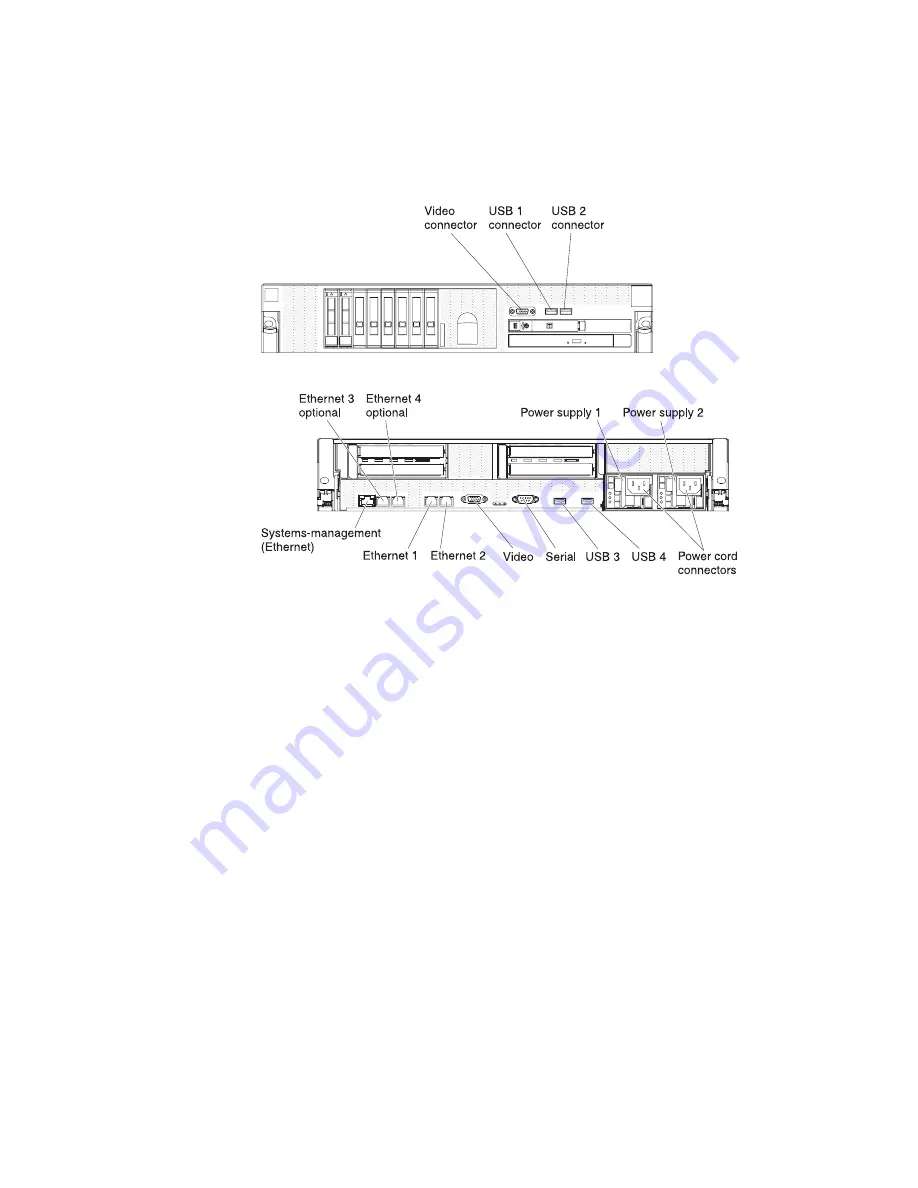
The following illustrations show the locations of the input and output connectors on
the front and rear of the server.
Front view
Rear view
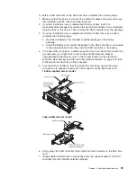
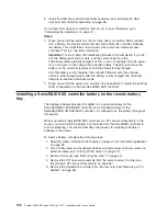
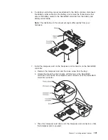
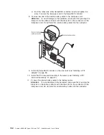
See the documentation that comes with any external devices for additional cabling
instructions. It might be easier for you to route cables before you connect the
devices to the server.
Cable identifiers are printed on the cables that come with the server and optional
devices. Use these identifiers to connect the cables to the correct connectors.
If the server comes with an installed operating system, see the documentation that
comes with the operating system for additional cabling instructions.
Chapter 2. Installing optional devices
113
Summary of Contents for 7947E3U
Page 1: ......
Page 2: ......
Page 3: ...System x3650 M2 Types 4199 and 7947 Installation and User s Guide...
Page 8: ...vi System x3650 M2 Types 4199 and 7947 Installation and User s Guide...
Page 16: ...xiv System x3650 M2 Types 4199 and 7947 Installation and User s Guide...
Page 40: ...24 System x3650 M2 Types 4199 and 7947 Installation and User s Guide...
Page 150: ...134 System x3650 M2 Types 4199 and 7947 Installation and User s Guide...
Page 168: ...152 System x3650 M2 Types 4199 and 7947 Installation and User s Guide...
Page 169: ......
Page 170: ...Part Number 81Y6111 Printed in USA 1P P N 81Y6111...

