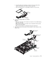
Internal cable routing and connectors
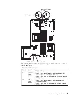
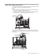
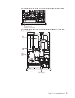
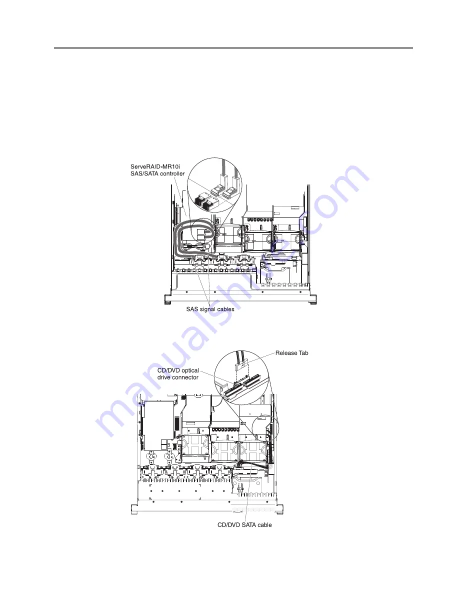
The following illustration shows the internal routing and connectors for the two SAS
signal cables (in server models with eight SAS drive bays).
Notes:
1. To connect the SAS signal cables, make sure that you first connect the signal
cable, and then the power cable and signal cable.
2. To disconnect the SAS signal cables, make sure that you first disconnect the
power cable, and then the signal cable and configuration cable.
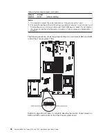
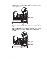
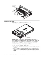
The SATA cable is a combination power and signal cable with a shared connector
on both ends. The following illustration shows the internal routing and connector for
the SATA cable.
Chapter 2. Installing optional devices
41
Summary of Contents for 7947E3U
Page 1: ......
Page 2: ......
Page 3: ...System x3650 M2 Types 4199 and 7947 Installation and User s Guide...
Page 8: ...vi System x3650 M2 Types 4199 and 7947 Installation and User s Guide...
Page 16: ...xiv System x3650 M2 Types 4199 and 7947 Installation and User s Guide...
Page 40: ...24 System x3650 M2 Types 4199 and 7947 Installation and User s Guide...
Page 150: ...134 System x3650 M2 Types 4199 and 7947 Installation and User s Guide...
Page 168: ...152 System x3650 M2 Types 4199 and 7947 Installation and User s Guide...
Page 169: ......
Page 170: ...Part Number 81Y6111 Printed in USA 1P P N 81Y6111...

