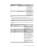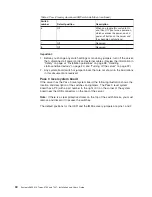
Table 4. Pass 8 level system board SW3 switch definition (continued)
Switch
number
Default position
Description
6
Off
When you toggle this switch to On
and then Off, you force a power-on,
which overrides the power-on and
power-off button on the server and
they become nonfunctional.
7
Off
Reserved.
8
Off
Reserved.
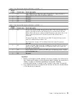
Important:
1. Before you change any switch settings or move any jumpers, turn off the server;
then, disconnect all power cords and external cables. (Review the information in
“Safety” on page vii, “Installation guidelines” on page 38, “Handling
static-sensitive devices” on page 40, and “Turning off the server” on page 22.)
2. Any system-board switch or jumper blocks that are not shown in the illustrations
in this document are reserved.
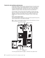
Pass 9 level system board
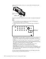
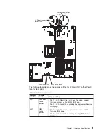
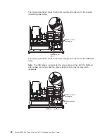
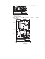
If the server has the Pass 9 level system board, the following illustration shows the
location and description of the switches and jumpers. The Pass 9 level system
board has a P9 (with a part number to the right of it) on the corner of the system
board near the USB connectors on the rear of the server.
Note:
If there is a clear protective sticker on the top of the switch blocks, you must
remove and discard it to access the switches.
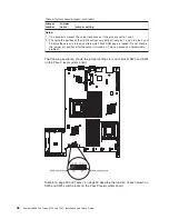
The default positions for the UEFI and the IMM recovery jumpers are pins 1 and 2.
30
System x3650 M2 Types 4199 and 7947: Installation and User’s Guide
Summary of Contents for 7947E3U
Page 1: ......
Page 2: ......
Page 3: ...System x3650 M2 Types 4199 and 7947 Installation and User s Guide...
Page 8: ...vi System x3650 M2 Types 4199 and 7947 Installation and User s Guide...
Page 16: ...xiv System x3650 M2 Types 4199 and 7947 Installation and User s Guide...
Page 40: ...24 System x3650 M2 Types 4199 and 7947 Installation and User s Guide...
Page 150: ...134 System x3650 M2 Types 4199 and 7947 Installation and User s Guide...
Page 168: ...152 System x3650 M2 Types 4199 and 7947 Installation and User s Guide...
Page 169: ......
Page 170: ...Part Number 81Y6111 Printed in USA 1P P N 81Y6111...

