7. Set the
S/M/VL Recording Time
. The DVMS/NVR will record for the number of seconds specified prior to and after
sensor activation, motion detection or any VideoLogix event up to a maximum of 10 seconds. The system keeps a
10-second video buffer that can be added to the beginning of recorded video segment in case of VideoLogix even,
sensor activation or motion detection. In the example above, the video channel(s) will record for 10 seconds prior to
sensor activation/motion detection/VideoLogix event and for 10 seconds after the sensor activation/VideoLogix event
or after the motion has stopped. The pre- and post-record length cannot exceed 10 seconds.
Caution
Motion and Schedule Setups must be prop-
erly configured for motion recording. Hard-
ware and Schedule Setups must be properly
configured for sensor recording. VideoLogix
and Schedule Setups must be properly con-
figured for VideoLogix recording.
8.
Click the
Save
button
to save the configured settings
Related Topics:
Hardware Setup-Channel Settings | Hardware Setup-Control Settings | Schedule Setup | Communic-
ation Setup | Server Info | System Setup | E-Map Setup | Email Setup | Video Setup | VideoLogix Setup
1.4.4. Hardware Setup - Spot Monitor Setup
1.4.4.1. Overview
Important
Only Administrator User, i3dvr, has permis-
sion to configure this setup.
Tip
Hardware Setup tab can be hidden from
select users in User Management setup tab.
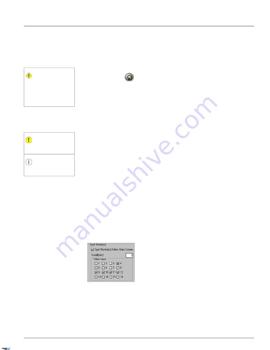
The Spot Monitor section allows the user to view selected video inputs on an spot monitor (if available). The spot monitor
should be connected to the DVMS I/O Board. Video inputs will be displayed one-by-one in a sequence with a configured
delay time.
Please note that Video Input is a physical camera and the Video Input number is determined by the BNC connector
number in the back of the DVMS.
1.4.4.2. Creating or Modifying Spot Monitor Settings
Before configuring this section, make sure that the spot monitor is properly connected to the DVMS.
If your system has ADIO-1616 I/O board installed, connect your spot monitor to the BNC connector on the I/O board.
If your system has AD-3016 capture card installed, connect your spot monitor to the second or third BNC port on the
capture board.
When spot monitor is connected to the AD-2016/AD-2816 capture board, the spot monitor will always follow the the
screen division set in Real-time display mode.
To configure an spot (external) monitor for sequential switching, do the following:
1. Select the video input number(s) to be shown in the sequence. You may select just one number to display the same
camera on the spot monitor. The Video Input number refers to the physical BNC connector number at the back of
the DVMS. (i.e. the Video Source in the Channel Settings setup). In this example, cameras 4, 9-12 will be shown in
a sequence on the spot monitor.
63
Hardware Setup - Spot Monitor Setup
Chapter 1. SRX-Pro Server
XML to PDF by RenderX XEP XSL-FO Formatter, visit us at
http://www.renderx.com/


