


33
In Short
To use
PowerSuite
to configure the power system via an Ethernet LAN connection, just connect the controller to the LAN. Using the “
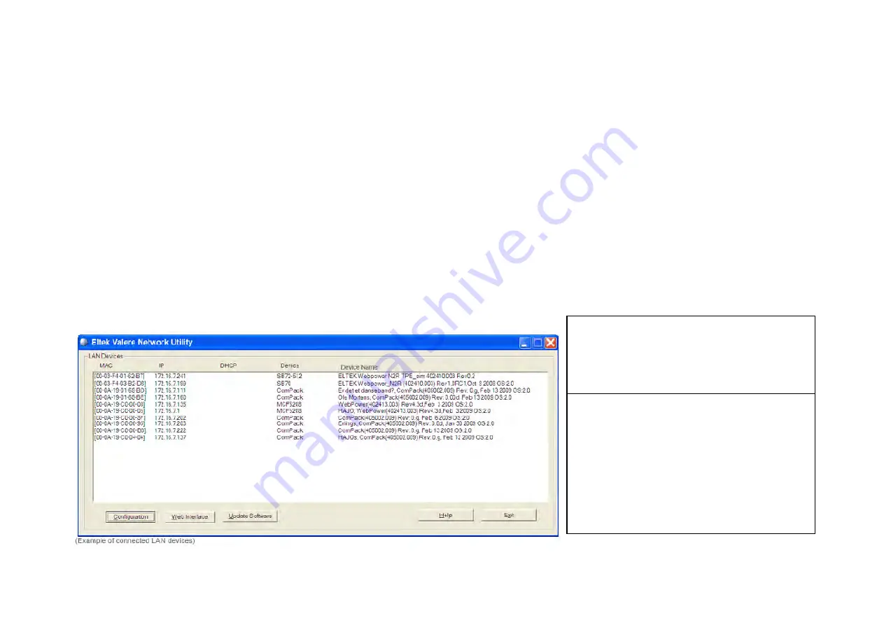
Eltek Valere Network Utility
” program,
identify the controller and make a note of its IP address. Start
PowerSuite
in your LAN connected computer, click on the “Connect” button and in the Site Manager dialog
box create a new Network site with the controller’s IP address.
The “Configuration — via PowerSuite Application” procedure involves following steps (as described in more detail in the next chapter):
1.
Start the “Eltek Valere Network Utility” program
2.
Connect the
Compack
controller to the LAN
3.
Identify the controller in the “
Eltek Valere Network Utility
” program
4.
Start the
PowerSuite
application in your computer (connected to the LAN)
5.
In
PowerSuite
’s Site Manager, create a new Network site for the controller
For more detailed description of configuration options and other advanced networking services implemented by the controller, click any time on the
PowerSuite
’s Help
buttons to browse and search through
PowerSuite Online Help
.
Also, refer to the
WebPower Online Help
file that you can download with the controller’s firmware. For acronym descriptions, refer to chapter “Glossary”, page
44
More Detailed
Carry out the following steps to use
PowerSuite
via an Ethernet LAN connection:
1.
Start the “
Eltek Valere Network
Utility
” program
by opening the file
“EVIPSetup.exe”, which will display already
connected LAN devices. The
Compack
controller will be displayed after connection
to the LAN.
2. Connect the
Compack
controller to
the LAN
plugging one end of a standard
Ethernet cable (straight through Ethernet
cable)
to the controller’s RJ
-45 socket on its
top, and the other end to one of the LAN’s
available RJ-
45 sockets. See “Figure 8”,
page
16
. The controller automatically
obtains an IP address from the LAN server,
as the controller’s DHCP protocol is enabled
from factory.
Summary of Contents for Compack
Page 2: ...2 Monitoring and Control Units Micropack DC Power Supply Systems 350011 013...
Page 13: ...13 Technical Specifications Controllers...
Page 14: ...14...
Page 42: ...42...
Page 47: ...47 Les Pages IHM GUI pages...
Page 48: ...48...
Page 49: ...49...
Page 50: ...50...
Page 51: ...51...
Page 52: ...52...
Page 53: ...53...
Page 54: ...54...
Page 55: ...55...
Page 56: ...56...
Page 57: ...57...
Page 58: ...58...
Page 59: ...59...
Page 60: ...60...
Page 61: ...61...
Page 62: ...62...
Page 63: ...63...
Page 64: ...64...
Page 65: ...65...
Page 66: ...66...
Page 67: ...67...
Page 68: ...68...


