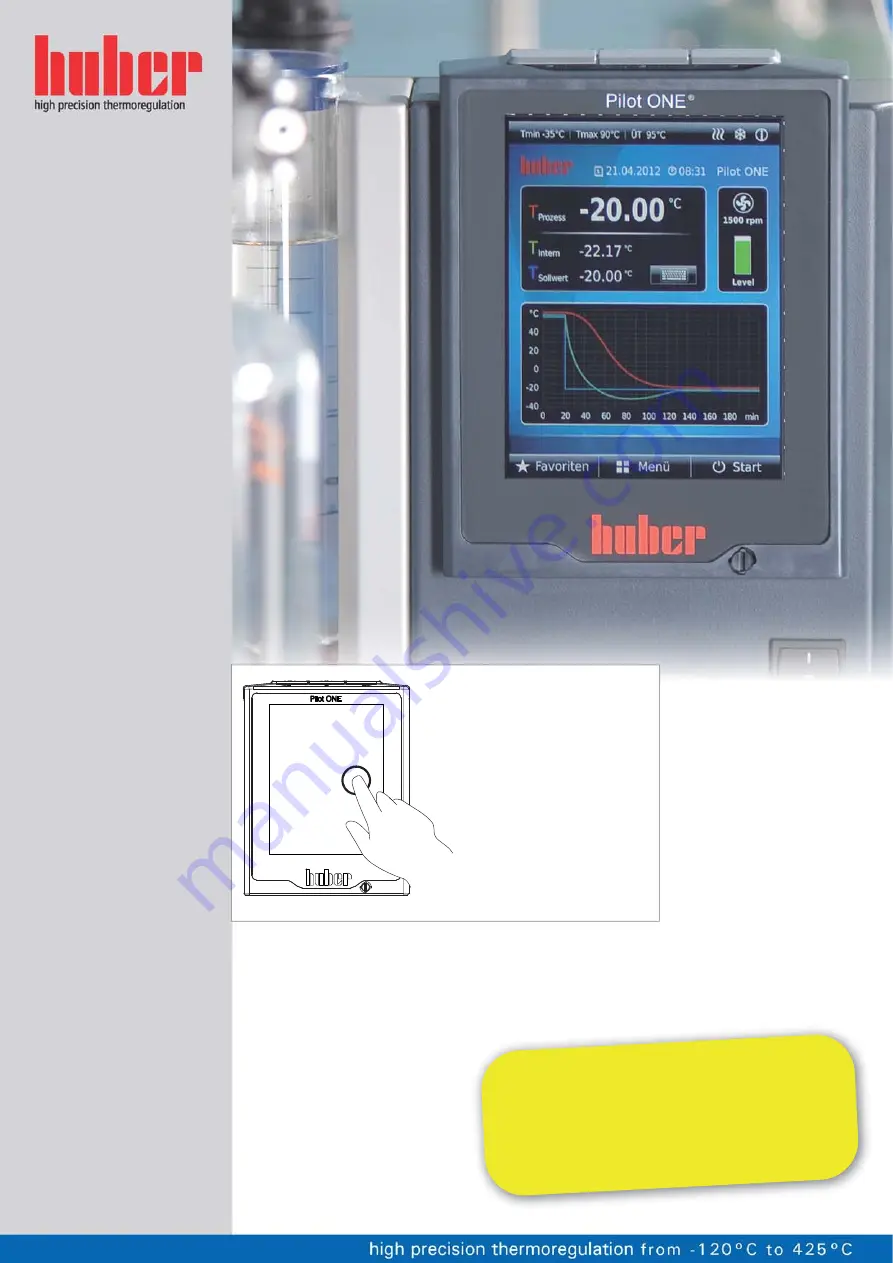
background image


Unistat®

T300


Series


V1.2.0


Operation


Manual

This documentaon does not con

tain a

device-specific technical appendix.

You can request the full oper

ang instrucons from 

[email protected]

om. Please give the model designa

on 

and serial number of 

your temperature co

ntrol unit 

in your e-mail.

Summary of Contents for Pilot ONE Unistat T300 Series

Page 1: ...This documenta on does not contain a device speci c technical appendix You can request the full opera ng instruc ons from info huber online com Please give the model designa on and serial number of y...

Page 2: ......

Page 3: ...OPERATION MANUAL Unistat T300 Series V1 2 0...

Page 4: ......

Page 5: ...bility for errors and misprints excluded Unistat T300 Series 5 Unistat T300 Series This operation manual is a translation of the original operation manual VALID FOR TABLE TOP MODELS Unistat T305 HT w...

Page 6: ...Unistat T300 Series Liability for errors and misprints excluded V1 2 0en 12 05 15 14 06 6 Unistat Control ONE and Pilot ONE Description of the LEDs in the flow dia gram Components illustrat ed in the...

Page 7: ...OPERATION MANUAL V1 2 0en 12 05 15 14 06 Liability for errors and misprints excluded Unistat T300 Series 7 Layout of the Home screen...

Page 8: ...rol unit for outdoor installation incl winter operation 21 2 6 Recommended temperature control and cooling water hoses 22 2 7 Wrench sizes and torques 22 2 8 Temperature control units with water cooli...

Page 9: ...0 4 Setup mode 41 4 1 Setup mode 41 4 1 1 Turning on the temperature control unit 41 4 1 2 Setting the overtemperature protection 41 4 1 2 1 General information on the overtemperature protection 42 4...

Page 10: ...tarting the temperature control process 66 5 1 1 2 Ending the temperature control process 66 5 1 2 Temperature control via a created temperature control program 67 5 1 2 1 Starting the temperature con...

Page 11: ...ement and circuit cleaning 81 7 4 1 Thermal fluid inspection 81 7 4 2 Thermal fluid replacement 81 7 4 2 1 Externally closed application 81 7 4 2 2 Externally open application 81 7 4 3 Cleaning the th...

Page 12: ...OPERATION MANUAL Unistat T300 Series Liability for errors and misprints excluded V1 2 0en 12 05 15 14 06 12...

Page 13: ...bau GmbH You have made a good choice Thank you for your confidence in our products Read through this operation manual carefully prior to start up Strictly follow all notes and safety in structions Pro...

Page 14: ...residual risk when disregarding the operation manual Denotes an immediate hazardous situation that will result in death or serious injuries Denotes a general hazardous situation that may result in de...

Page 15: ...ialists trained by the manufacturer may carry out modifications repairs or mainte nance work The following must be observed without fail Only use the temperature control unit in a fault free condition...

Page 16: ...is NOT permissible The temperature control unit must NOT be used for any purposes other than temperature control in accordance with the operation manual The manufacturer accepts NO liability for dama...

Page 17: ...C i e if ethanol is used only supervised operation is possible c The overheat protection can for instance can be realized using a suitable fill level sensor or a suitable temperature limiter d Option...

Page 18: ...N OFF AUTO Permanently ON Even if the temperature continues to rise the cooling machine will use its maximum cooling capacity to keep any further increase in temperature as low as possible You must ob...

Page 19: ...ply with the requirements under sections Ambient conditions and Installation condi tions Make sure there is adequate fresh air available at the site for the circulation pump and the com pressors The w...

Page 20: ...Air outlet on top of unit free standing A2 Top can be located under a bench can be located under a bench B Left min 20 min 10 C Right min 20 min 10 D Front min 20 min 10 E Rear min 20 min 20 Side of t...

Page 21: ...of a drain tray for the installation area of the temperature control unit the entire system Observe the floor load bearing capacity for large units Observe the ambient conditions 2 5 Temperature contr...

Page 22: ...ontrol hoses that are compatible with the thermal fluid used When selecting temperature control hoses also pay attention to the temperature range in which the hoses are to be used We recommend you use...

Page 23: ...ainst corrosion DAMAGE TO THE TEMPERATURE CONTROL UNIT The addition of anti corrosion agents is mandatory if salts chlorides bromide have been added to the water circuit Ensure that the materials used...

Page 24: ...for leaks 2 9 Preparations for operation 2 9 1 Opening closing valves Opening valves Open valves by turning them counterclockwise turn 90 left as far as it will go Close valves close valves by turnin...

Page 25: ...unit immediately Allow the thermal fluid to cool to room temperature Prior to starting up the temperature control unit with an externally closed system remove the Isolating sleeve 27 see page 24 in se...

Page 26: ...ockwise turn 90 right as far as it will go To enable your application to be operated correctly and eliminate air bubbles from the system you must ensure that the Circulation flow 1 connection from the...

Page 27: ...ol unit Isolate the temperature control unit from the power supply Have the power supply cable power supply connection replaced and inspected by an electri cian Do not use a power cable that is longer...

Page 28: ...ble top models and some free standing models enables the speed or the pressure of the thermal fluid to be controlled and hence optimally matched to the specified application On free standing models wi...

Page 29: ...l fluid must not exceed 50 mm s at the lowest working temperature The maximum density of the thermal fluid may not exceed 1 kg dm Inert gas blanket over the Expansion vessel 18 over 0 1 bar g MATERIAL...

Page 30: ...but is also suitable as regards the combustion point boiling point and viscosity In addition the thermal fluid must be compatible with all the materials in your system Avoid bending the temperature c...

Page 31: ...n for control sensor internal Pt100 external Pt100 and return flow sensor 2 point 5 point 5 point Monitoring low level overtemperature 2 Adjustable alarm thresholds VPC Variable Pressure Control 3 Ven...

Page 32: ...tact ALARM 2 AIF Analog Interface 0 4 20 mA or 0 10 V 3 Digital interface RS485 4 Comfort other Visual audible alarm signal Autostart Power Failure Auto Plug Play technology Technology glossary Remote...

Page 33: ...by a rechargeable accumulator which is automatically charged when the temperature control unit is switched on The accumulator is dimensioned so that the clock can also continue to run for prolonged s...

Page 34: ...be necessary to confirm the cancella tion again When canceling a dialog sequence settings made earlier in the dialog sequence are discarded Check your already carried out settings and re enter as need...

Page 35: ...rrow After 2 minutes of inactivity the category sub category or the Favourites menu is automatically closed and you return to the Home screen Dialogs are not can celed closed after 2 minutes of inacti...

Page 36: ...ronics will be displayed Tap either the ESC or OK touchbutton You will be returned to the previous screen Tap on the Home touchbutton house to return to the Home screen 3 10 2 Start Stop How to start...

Page 37: ...on allows this Restoring the factory settings cannot be revoked Depending on the type of resetting to facto ry settings performed you may have to enter parameters process safety thermal fluid used cut...

Page 38: ...00 Baud Device address 1 ECS Standby No impact POKO alarm Off Attributes other Change thermal fluid Thermal fluid No data No of liters 0 Use of bypass No Chilling bath cooling CC E only None Sensor ca...

Page 39: ...ction for switching from RidR to standard struc ture Off Safety function Upper alarm threshold internal Max working temperature 20 K Lower alarm limit internal Min working temperature 20 K Upper alarm...

Page 40: ...entry Tap on the OK touchbutton to confirm your choice Read the message displayed Tapping on Yes restores the factory settings tapping on No cancels the procedure Inthefollowingdialog entertheovertem...

Page 41: ...ng on OK Tap on the thermal fluid used Confirm your choice by tapping on OK Read the message and confirm by tapping on OK Enter the volume using the number keypad that appears Confirm your entry by ta...

Page 42: ...can also under certain circumstances result in a shutdown of the temperature control unit In this case however a shutdown would be fatal Our temperature control units provide the possibility to work w...

Page 43: ...cess Safety Once the overtemperature protection cut out value is reached the heater switches off and the cooling circuit and circulation pump continue to operate In case of an emergency possible exo t...

Page 44: ...ratus DAMAGE CAUSED BY GLASS APPARATUS BURSTING Adjust the Delta T value to your application The temperature dynamics inside the reactor process temperature are dictated by the flow tem perature A dif...

Page 45: ...stest possible time This increases the productivity of the system as a whole and thus saves energy in the long term 4 2 1 Select temperature control Internal or process PROCEDURE Go to the Categories...

Page 46: ...e connection cable should not be unnecessarily long Make sure that the process sensor is properly attached at the measurement point and that there is good thermal coupling The sensor itself must have...

Page 47: ...epth knowledge of process measur ing and control technology Incorrect or insufficient settings can severely impair the function of the temperature control unit In Expert mode Configuration auto is dea...

Page 48: ...modify an existing control parameter set by entering the thermal fluid used and the quantity of thermal fluid This version is available with bath thermostats without connected external application All...

Page 49: ...to the temperature control unit and the application during parameter determination Go to the Categories Menu Tap on the category Temperature Control Tap on the category TAC Manual Tap on the sub cate...

Page 50: ...time without reactivating the Find control pa rameters PROCEDURE Go to the Categories Menu Tap on the category Temperature Control Tap on the category TAC Manual Tap on the sub category Configuration...

Page 51: ...iguration auto Tap on the sub category Fluid Properties Tap on the sub category Bath Circulation Volume Read the message and confirm it by tapping on OK Enter the filling volume using the number keypa...

Page 52: ...ure control unit 4 2 9 1 Sub category Change parameters In this menu you manually configure the control parameters If only the internal temperature is used as a target value the control parameters are...

Page 53: ...value using the number keypad that appears Confirm your entry by tapping on OK Enter the new Tn value using the number keypad that appears Confirm your entry by tapping on OK Enter the new Tv value us...

Page 54: ...d Depending on the previous setting these will be the Automatic control parameters or the Manual control parameters PROCEDURE Go to the Categories Menu Tap on the category Temperature Control Tap on t...

Page 55: ...he value just entered either with the Arrow key or with the clear key Enter the setpoint again Confirm your entry by tapping on OK In the display that follows confirm your entry again by tapping on OK...

Page 56: ...f 95 C The cooling water outlet temperature is then 60 C The standard operating temperature is preset to 95 C and is reset to 95 C at every reboot PROCEDURE Example 1 Compensation of self heating to w...

Page 57: ...HT series is equipped with a cooling water connection with controlled cooling water consumption These temperature control units not only enable the implementation of positive temperature gradients e...

Page 58: ...e the following volumes for this calculation Minimum filling capacity of the temperature control unit Volume of the Extra expansion vessel 19 optional Volume of the thermal fluid hoses Jacket volume o...

Page 59: ...Expansion vessel 18 COMBUSTION PROPERTY DAMAGE Due to the rapid heating of the low boiling component contained in the mixture a sudden overflow from the Expansion vessel 18 is to be expected Hot surf...

Page 60: ...mal fluid circuit Go to the Categories Menu Tap on the category Temperature Control Tap on the category Start Stop Tap on the dialog entry Start degassing Confirm your choice by tapping on OK Read the...

Page 61: ...he Expansion vessel cap 22 by hand Carefully pour new original thermal fluid using the filling accessories funnel and or beaker into the Filling port 17 You can see the fill level in the Sight glass 2...

Page 62: ...turning them clockwise turn 90 right as far as it will go 4 4 2 1 Filling and venting externally open application Non compliance with the safety data sheet for the thermal fluid to be used INJURIES R...

Page 63: ...8 and by opening the Drain valve thermofluid 3 by turning it counterclockwise turn 90 to the left as far as it will go In case of too little thermal fluid the pump draws air instead of thermal fluid...

Page 64: ...is displayed graphically for 2 seconds After this the display will return to the Home screen again Try to stop the temperature control unit again The degassing process is complete 4 4 2 3 Draining ex...

Page 65: ...le for to allow it to dry out and the residue to drain Without screw caps with Drain valve 4 open Close the Drain valve 4 by turning it clockwise turn 90 right as far as it will go Close the connectio...

Page 66: ...control process When the temperature control unit is switched off the thermal fluid temperature is high er lower than room temperature DAMAGE TO THE TEMPERATURE CONTROL UNIT AND THE GLASS APPARATUS AP...

Page 67: ...Bring the thermal fluid up to room temperature using the temperature control unit Do not close the shut off valves in the thermal fluid circuit You can either end the temperature control automaticall...

Page 68: ...network sockets This is a fast and flexible interface Standard 10 100 Mbps interface Fast Ethernet can be connect ed to any existing Ethernet network Because this interface can also be connected to ve...

Page 69: ...damaged Before connecting ensure the temperature control unit and the device to be connected are turned off 6 2 1 1 Removing the cover PROCEDURE Insert a screwdriver into the opening Prise of the cove...

Page 70: ...the temperature control unit is ready for opera tion The unit is ready for operation about 30 seconds after switching on once the internal con troller check has been completed The OK status is termin...

Page 71: ...ative to the internal sensor absolute temperature The POCO is active outside of this range the POCO is in active inside of this range Process temperature absolute This enables you to set a temperature...

Page 72: ...e strictly observed The control results contained in the data sheet can only be achieved with shielded sensor leads We recommend the external Pt100 sensors from the Huber accessories Pin Signal 1 I 2...

Page 73: ...nternal con troller check has been completed The OK status is terminated by switching off the unit or in case a fault occurs Internal temperature relative Set the upper and lower limit of a temperatur...

Page 74: ...is active outside of this range the POCO is in active inside of this range Process temperature absolute This enables you to set a temperature range relative to the process temperature absolute temper...

Page 75: ...itches between these two tem perature sensors Temperature control on off The temperature control process starts when switching from an open to a closed contact The temperature control process switches...

Page 76: ...onnect the temperature control unit from the power supply by turning the Mains isola tor 36 on the temperature control unit to 0 Also disconnect the temperature control unit from the current supply In...

Page 77: ...t the temperature control unit to the power supply Switch the temperature control unit on 7 3 Maintenance Cleaning maintenance while the temperature control unit is operating MORTAL DANGER FROM ELECTR...

Page 78: ...seal Responsible body and or operators L Check liquefier fins As required after 3 months at the latest See page 79 section Clean liquefier fins air cooled temperature control unit Responsible body and...

Page 79: ...liquefier fins Clean the liquefier fins using suitable cleaning appliances Make sure the liquefier fins are not damaged or deformed as this will impair the air flow Re mount the ventilation grille aft...

Page 80: ...tch the temperature control unit on PROCEDURE Free standing models Switch off the temperature control unit Do this by turning the Mains isolator 36 to 0 Disconnect the temperature control unit from th...

Page 81: ...EXCHANGER AND OR ELECTROMECHANICAL PARTS Regularly check your thermal fluid whether it meets the specifications in the safety data sheet Oxidation Oxidation ages the thermal fluid and changes its cha...

Page 82: ...es after draining Leave the temperature control unit with open valves for a while Leave the drain hose mounted to the Drain 8 Check the fill level in the collecting container at the end of the drain h...

Page 83: ...xternally open application does not need to be vented Start the degassing function as described on page 59 in section Degassing externally closed applications An externally open application does not n...

Page 84: ...ype and quantity of the materials used Consult the relevant safety data sheet You will find a prepared return receipt at www huber online com You as the responsible body are responsible for carrying o...

Page 85: ...fluid to be used INJURIES Risk of injury to the eyes skin respiratory tract The safety data sheet for the thermal fluid to be used must be read prior to use and its con tents respected Observe the lo...

Page 86: ...ng water slowly Building side shut off valves are not closed DAMAGE BY ROOM FLOODING Close the building s shut off valves in the cooling water supply and return lines For table top models place a coll...

Page 87: ...control unit alone and without aids Always use the original packaging for transport Always transport the temperature control unit upright on a pallet Protect attachments from damage during transport...

Page 88: ...re control unit to hand The serial number can be found on the rating plate on the temperature control unit 8 7 1 Telephone number Customer Support Telephone 49 781 9603 244 8 7 2 Telephone number Sale...

Page 89: ...Annex Chapter 9 OPERATION MANUAL V1 2 0en 12 05 15 14 06 Liability for errors and misprints excluded Unistat T300 Series 89 9 Annex...

Page 90: ...Ger tes Extend the Warranty of Your HUBER Unit Register now Garantie Warranty Peter Huber K ltemaschinenbau GmbH Werner von Siemens Stra e 1 D 77656 Offenburg Germany tel 49 781 9603 0 fax 49 781 5721...

Reviews: