2-3
Racing Kit
Adjusting the Compression Ratio
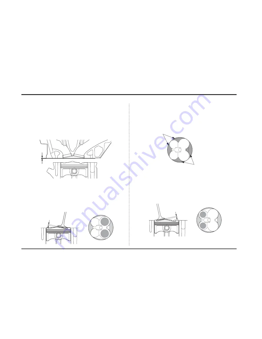
Grind the cylinder head mating surface using the following procedure.
1. Remove the cylinder head and remove carbon deposits from the combus-
tion chambers.
2. Grind the cylinder head mating surface 0.15 mm (0.006 in) by machining
roughness 8S. Finish the surface using an oil stone.
3. Remove the carbon deposits from the piston heads. Reassemble the piston
and cylinder head using a standard gasket
Expected compression ratio: 12.6 : 1
0.15 mm
(0.006 in)
Select the cylinder head gasket as follows:
1. With the aid of a dial gauge, position the piston at TDC (Top Dead Center).
2. Measure the clearance between the intake valve and the piston head using
a solder.
When the clearance is hin<1.2 mm:
Use a racing kit gasket (t=0.65 mm), because there is a possibility that the
piston may contact with the valve.
When the clearance is hin _
≥
1.2 mm: go to step 3.
3. Measure the clearance between the squish area of the piston head and com-
bustion chamber using a solder.
When the clearance is hsq<0.65 mm:
Use a racing kit gasket (t=0.65 mm), because there is a possibility that the
piston may contact the combustion chamber.
When the clearance is hin _
≥
0.65 mm: go to step 4.
4. Measure the clearance between the exhaust valve and piston head using a
solder.
When the clearance is hin<1.4 mm:
Use a racing kit gasket (t=0.65 mm), because there is a possibility that the
piston may contact the valve.
When the clearance is hin _
≥
1.4 mm:
Use standard gasket (t=0.60 mm).
Squish area
Squish area
hin
hex


