Removal and replacement procedures 32
Cable connections
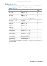
Table 3-1 provides cabling information for the server chassis. For more detailed information about
system board components, see System board components in Chapter 5.
Table 3-1
Cable connection
From
To
# of pins
Power supply, P1
System board, J39
24
Power supply, P2
System board, J14
4
Power supply, P3
System board, J37
8
Power supply, RPS
System board, J25
16
Power supply, P8, 9, 14, 15
ATX drives and/or hot-plug HDD backplane
4
Power supply, P4-7, 10-13
SATA drives
15
System Fan 1
System board, J54
6
System Fan 2
System board, J44
6
System Fan 3
System board, J38
6
System Fan 4
System board, J4
6
Front USB 2.0 ports
System board, J30
10
System board SATA1
SATA hard drive #1 [1], J40
7
System board SATA2
SATA hard drive #2 [1], J51
7
System board SATA3
SATA hard drive #3 [1], J52
7
System board SATA4
SATA hard drive #4 [1], J41
7
System board SATA5
SATA optical drive #1, J29
7
System board SATA6
SATA optical drive #2, J26
7
NOTE:
[1] For systems with hot-pluggable hard disk drives, hard drives #1-4 are terminated into one connector that attaches to the
hot-plug SAS/SATA module.
All manuals and user guides at all-guides.com
Summary of Contents for ProLiant ML150 G6
Page 12: ...Customer self repair 12 All manuals and user guides at all guides com ...
Page 13: ...Customer self repair 13 All manuals and user guides at all guides com ...
Page 14: ...Customer self repair 14 All manuals and user guides at all guides com ...
Page 15: ...Customer self repair 15 All manuals and user guides at all guides com ...

