background image

NOTE:

Mezzanine slot 1 must contain the P711m Controller, another mezzanine card, or the mezzanine
card blank. If you are installing the P711m card in mezzanine slot 1, do so now following the
instructions “Installing the P711m Controller Board.” If you are not installing the P711m card in
mezzanine slot 1, and no other mezzanine card is present in slot 1, then install the mezzanine
card blank at this time.

5.

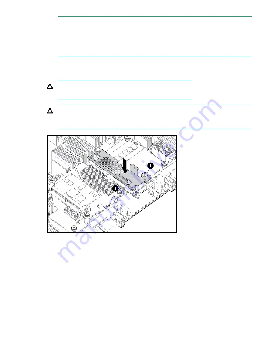
Clip the mounting bracket onto the mezzanine card or mezzanine card blank.

6.

Press the bracket thumbscrew clip over the thumbscrew closest to the mezzanine post.

7.

Push the remaining bracket foot over the other edge of the mezzanine card or mezzanine card blank.

CAUTION:

Push only enough to anchor the bracket, keeping the bracket level.

CAUTION:

To avoid damage to the power cable ensure the battery bracket does not pinch the power cable
to the power connectors.

8.

Replace any mezzanine cards that you had to remove from mezzanine slot 2 (

Mezzanine cards

 on

page 127).

To remove the component, reverse the procedure.

Installing the P711m controller board

This card is supported in slots 1, 2, and 3 on the BL860c i4, BL870c i4, and BL890c i4 server blades.

Installing the P711m controller board

57

Summary of Contents for Integrity BL860c i4

Page 1: ...70c i4 BL890c i4 Server Blade User Service Guide Part Number 5200 2523 Published September 2017 Edition 6 Abstract This document contains specific information that is intended for users of this Hewlett Packard Enterprise product ...

Page 2: ...ckard Enterprise has no control over and is not responsible for information outside the Hewlett Packard Enterprise website Acknowledgments Intel Itanium Pentium Intel Inside and the Intel Inside logo are trademarks of Intel Corporation in the United States and other countries Microsoft and Windows are either registered trademarks or trademarks of Microsoft Corporation in the United States and or o...

Page 3: ...er or device bay divider 19 Installing interconnect modules 21 Installing the server blade into the enclosure 22 Server blade power states 24 Powering on the server blade 24 Powering off the server blade 25 Installing the Blade Link for BL860c i4 BL870c i4 or BL890c i4 configurations 25 Using iLO 3 29 Accessing UEFI or the OS from iLO 3 MP 29 UEFI Front Page 30 Saving UEFI configuration settings 3...

Page 4: ...ing the access panel 59 Upgrading a conjoined configuration 59 Procedure summary 60 Upgrade kit contents 60 Before getting started 61 Upgrading the original server 67 Support 75 Blade link and system information parameters 75 Operating System Licenses 76 The Quick Boot option 77 Possible changes due to VC profile mapping on the upgraded blade server 77 Preserving VC assigned MAC addresses in HP UX...

Page 5: ...ng 112 Powering off the server blade 113 Blade Link for BL870c i4 or BL890c i4 configurations 113 Removing the Blade Link for BL870c i4 or BL890c i4 configurations 113 Replacing the Blade Link for BL870c i4 or BL890c i4 configurations 114 Blade Link for BL860c i4 configurations 115 Server blade 116 Access panel 117 Disk drive blanks 118 Removing a disk drive blank 118 Disk drives 118 DIMM baffle 1...

Page 6: ...elete Boot Option 148 Change Boot Order 149 Driver Options 150 Add Driver Option 151 Delete Driver Option 151 Change Driver Order 152 Console Configuration 152 Boot From File 153 Set Boot Next Value 154 Set Time Out Value 155 Reset System 155 iLO 3 MP 156 Warranty and regulatory information 157 Warranty information 157 Regulatory information 157 Belarus Kazakhstan Russia marking 157 Turkey RoHS ma...

Page 7: ...W 163 Contents 7 ...

Page 8: ...cifically the 10U c7000 and the 6U c3000 Enclosures The nPartition configuration feature is enabled from the factory enabling the BL870c i4 and BL890c i4 to be partitioned into one more electrically isolated partitions See the nPartitions Administrator Users Guide for more information NOTE For purposes of this guide make sure that the c Class server blade enclosure is powered on and running proper...

Page 9: ...nnector 3 type 1 or 2 3 Mezzanine connector 1 type 1 10 CPU1 power connector 4 Mezzanine connector 2 type 1 or 2 11 CPU1 5 System board thumbscrew 12 SAS backplane 6 System board thumbscrew 13 Pull tab 7 Battery CR2032 NOTE The iLO 3 password is located on the pull tab Server blade components 9 ...

Page 10: ... dimensions and weight for the BL860c i4 Dimensions value Height 36 63 cm 14 42 in Width 5 14 cm 2 025 in Depth 48 51 cm 19 1 in Weight Unloaded 8 6 kg 19 lb Fully loaded 11 3 kg 25 lb Table 2 Blade Link dimensions and weight Blade Link type Height Width Weight BL1 BL860 i4 44 mm 1 73 in 51 mm 2 in 5 lb 22 kg BL2 BL870 i4 44 mm 1 73 in 106 mm 4 17 in 1 lb 45 kg BL4 BL890 i4 44 mm 1 73 in 212 mm 8 ...

Page 11: ... minimum of 70 KPa For more information on the c Class enclosures see http www hpe com support Bladesystem_c3000_Enclosures_Manuals http www hpe com support Bladesystem_c7000_Enclosures_Manuals For more site preparation information go to http www hpe com info Blades docs select HPE Integrity BL860c i4 Server Blade in the list of servers and then select the Generalized Site Preparation Guidelines S...

Page 12: ... minimum and rear 36 inches 91 4 cm minimum are recommended clearances 3 Is access to the site or computer room restricted 4 Is the computer room structurally complete Expected date of completion 5 Is a raised floor installed and in good condition 6 Is the raised floor adequate for equipment loading 7 Are channels or cutouts available for cable routing 8 Is a network line available 9 Is a telephon...

Page 13: ... installed inside the building 18 Is power conditioning equipment installed 19 Is a dedicated branch circuit available for equipment 20 Is the dedicated branch circuit less than 75 feet 22 86 m 21 Are the input circuit breakers adequate for equipment loads Safety Number Area or Condition Yes No 22 Is an emergency power shutoff switch available 23 Is a telephone available for emergency purposes 24 ...

Page 14: ... for tape and disc media 32 Is shelving available for documentation Training Number Area or Condition 33 Are personnel enrolled in the System Administrator s Course 34 Is on site training required Power subsystem The power subsystem is located on the system board The BL860c i4 Server Blade receives 12 Volts directly from the enclosure The voltage is immediately passed through an E fuse circuit whi...

Page 15: ...ts by the edges only Do not touch any metal edge connectors or electrical components on accessory boards Unpacking and inspecting the server blade Be sure that you have adequately prepared your environment for your new server blade received the components that you ordered and verified that the server and the containers are in good condition after shipment Verifying site preparation Verifying site ...

Page 16: ...rder packing slip lists the equipment shipped from Hewlett Packard Enterprise Use this packing slip to verify that the equipment has arrived NOTE To identify each item by part number see the sales order packing slip Returning damaged equipment If the equipment is damaged immediately contact your Hewlett Packard Enterprise customer service representative The service representative initiates appropr...

Page 17: ...Download latest firmware and update using HP Smart Update Manager 9 Install and boot the OS NOTE For more information regarding HPE Integrity Server Blade upgrades see Upgrading a conjoined configuration on page 59 for more information Installing and powering on the server blade Preparing the enclosure HPE BladeSystem enclosures ship with device bay dividers to support half height devices To insta...

Page 18: ...re 1 Slide the device bay shelf locking tab to the left to open it 2 Push the device bay shelf back until it stops lift the right side slightly to disengage the two tabs from the divider wall and then rotate the right edge downward clockwise 18 Removing a c7000 device bay divider ...

Page 19: ...isengage the three tabs from the divider wall and then remove it from the enclosure Removing a c3000 device bay mini divider or device bay divider Procedure 1 Slide the locking tab down Removing a c3000 device bay mini divider or device bay divider 19 ...

Page 20: ... the divider drops out of the enclosure b c3000 divider I Push the divider toward the back of the enclosure until it stops II Slide the divider to the left to disengage the tabs from the wall III Rotate the divider clockwise IV Remove the divider from the enclosure 20 Installing the server blade into the enclosure ...

Page 21: ... steps to install interconnect modules see the documentation that ships with the interconnect module Interconnect bay numbering and device mapping HPE BladeSystem c7000 Enclosure HPE BladeSystem c3000 Enclosure Installing interconnect modules 21 ...

Page 22: ...tailed port mapping information see the BladeSystem enclosure installation poster or the BladeSystem enclosure setup and installation guide for your product on the Hewlett Packard Enterprise website http www hpe com info Blades docs Installing the server blade into the enclosure NOTE When installing additional blades into an enclosure additional power supplies might also be needed to meet power re...

Page 23: ...any server blade options such as an additional processor hard drive or mezzanine card Procedure 1 Remove the connector covers if they are present 2 Prepare the server blade for installation 3 Install the server blade Installing the server blade into the enclosure 23 ...

Page 24: ...ower States Server Blade Installed in Enclosure Front Panel Power Button Activated Standby Power Applied DC Power Applied Standby power Yes No Yes No Full power Yes Yes Yes Yes Off No No No No Powering on the server blade Use one of the following methods to power on the server blade NOTE To power on blades in a conjoined configuration only power on the Monarch blade See Blade Link bay location rul...

Page 25: ...s the server blade to enter standby mode without properly exiting applications and the OS It provides an emergency shutdown method in the event of a hung application Installing the Blade Link for BL860c i4 BL870c i4 or BL890c i4 configurations IMPORTANT Without an attached Blade Link the server blades will not power on NOTE Before installing the Blade Link for BL870c i4 or BL890c i4 make sure the ...

Page 26: ... Bottom half height adjacent bay paired with the server blade in full height bays 1 2 3 4 5 6 or 7 8 c3000 Half height bay 8 paired with the server blade in full height bay 3 CAUTION The bay mini divider must be installed in the c3000 enclosure to ensure the partner blade is inserted correctly Failure to install the bay mini divider might result in damage to the blade or enclosure when installing ...

Page 27: ...i4 c3000 only Bays 1 2 3 4 with Monarch blade defaulting to slot 1 No N A 1 For information on installing the c3000 bay mini divider see the HPE BladeSystem c3000 Enclosure Setup and Installation Guide CAUTION Using the incorrect Blade Link can cause damage to the Blade Link and to the connectors on both the Blade Link and the server blades IMPORTANT Failure to follow bay location rules can preven...

Page 28: ...If not properly aligned you can damage the Blade Link 11 Close the handle when it has engaged 12 Log into iLO 3 on the Monarch blade For more information see the HPE Integrity iLO3 Operations Guide 13 In iLO 3 go to the Command Menu and execute xd r to reboot all of the iLO 3s in the conjoined set 14 Run the conjoin checks Integrity BL870c i4 and BL890c i4 systems go through a process called conjo...

Page 29: ... independent of the host server and operating system The iLO 3 subsystem provides remote access to any authorized network client sends alerts and provides other server management functions Using iLO 3 you can Remotely power on power off or reboot the host server Subscribe to we man alerts from iLO 3 regardless of the state of the host server Access advanced troubleshooting features through the iLO...

Page 30: ...y even disable this feature be sure wait for the prompt before hitting Ctrl C NOTE It can take several minutes for this prompt to appear and the window of time when Ctrl C can be pressed is very short For typical boots Hewlett Packard Enterprise recommends that you let the prompt time out 5 Depending on how the server blade was configured from the factory and if the OS is installed at the time of ...

Page 31: ...To view boot options or launch a specific boot option press B or b to launch the Boot Manager Installing the server blade into the enclosure 31 ...

Page 32: ...anager This is an advanced feature and should only be performed when directed To perform maintenance on the system such as adding deleting or reordering boot options press M or m to launch the Boot Maintenance Manager 32 Installing the server blade into the enclosure ...

Page 33: ...system is loaded onto the server blade If the OS is loaded on your server blade normally UEFI will automatically boot to the OS If the UEFI Front Page is loaded press ENTER to start auto boot or B or b to select a specific boot option for your OS Use your standard OS logon procedures or see your OS documentation to log on to your OS Operating system is not loaded onto the server blade There are tw...

Page 34: ...ndled in a manner that reduces any downtime required for the update process HP SUM does not require an agent for remote installations Key features of HP SUM are GUI and CLI command line interface Dependency checking which ensures appropriate installation order and dependency checking between components Intelligent deployment deploys only required updates Support for updating firmware on network ba...

Page 35: ...o one of the USB ports on the SUV cable NOTE Some DVD drives might also require a separate power connection c Turn on the external USB DVD device 2 Insert the OS media into the USB DVD device or tape device 3 Power on the server blade and boot to UEFI If the server blade is already powered on then reboot to UEFI using the reset command at the UEFI prompt 4 From the UEFI Front Page press S or s to ...

Page 36: ...e locate the device I To boot from tape once you are at the UEFI shell Shell tapeboot select 01 PcieRoot 0x30304352 Pci 0x8 0x0 Pci 0x0 0x0 SAS 0x50060B00007F6FFC 0x0 0x1 NoTopology 0 0 0 0x0 Select Desired Tape 01 input 01 If the correct media is installed it will boot from tape when you enter the index number If there is no media in the SAS tape drive and you select 1 the following message appea...

Page 37: ...nce Manager or operating system utilities Autoboot setting The autoboot setting determines whether a server automatically loads the first item in the boot options list or remains at the UEFI Front Page menu With autoboot enabled UEFI loads the first item in the boot options list after a designated timeout period Configure the autoboot setting for an Integrity server using either the autoboot UEFI ...

Page 38: ...le file system number2 The UEFI Shell prompt changes to reflect the file system currently accessed The full path for the HP UX loader is EFI HPUX HPUX EFI and it should be on the device you are accessing 3 At the UEFI Shell environment use the bcfg command to manage the boot options list The bcfg command includes the following options for managing the boot options list a bcfg boot dump Display all...

Page 39: ...to the MP Main Menu To exit the MP Main Menu press X or x Booting HP UX from the UEFI Shell Procedure 1 Access the UEFI Shell 2 From the UEFI Front Page press S or s to launch the UEFI shell 3 Use the map command to list the file systems fs0 fs1 and so on that are known and have been mapped 4 To select a file system to use enter its mapped name followed by a colon For example to operate with the b...

Page 40: ...ser mode Booting HP UX in single user mode on page 40 except use the lm boot option instead of the is boot option HPUX boot lm vmunix Shutting down HP UX For more information see the shutdownvolume 1M manpage Procedure 1 Log in to HP UX running on the server that you want to shut down or log in to iLO 3 MP for the server and use the Console menu to access the system console Accessing the console t...

Page 41: ...tion For more information on partner bay blade locations see Installing the Blade Link for BL860c i4 BL870c i4 or BL890c i4 configurations on page 25 NOTE SAS tape boot is now supported with tape blades on HPE Integrity BL860c i4 BL870c i4 and BL890c i4 server blades NOTE PCIe Gen 1 driven from the ICH10 on the monarch blade s ICH mezzanine card provides the interface to the partner blades A separ...

Page 42: ... server blade see Server blade components list on page 109 Procedure 1 Remove the hard drive blank 2 Prepare the hard drive 3 Slide the drive into the cage until it is fully seated 4 Close the lever to lock the drive into place 42 Optional components ...

Page 43: ...nk module Processor load order Observe the following guidelines when installing additional processors In a BL860c i4 CPU0 is installed before CPU1 In a BL870c i4 or BL890c i4 each blade must have CPU0 installed When adding additional CPUs in a conjoined configuration Load both CPU0 and CPU1 in the Monarch blade first Load additional CPUs in sequence from lowest slot numbered blade to highest CAUTI...

Page 44: ... during installation into the server blade Procedure 1 Remove the CPU airflow baffle 2 Transfer the duplicate part serial numbers label from the processor module to the processor heatsink a Remove the duplicate tear away label that lists the part and serial numbers from the processor module b Place the label on the top of the heatsink 3 Install the processor over the load posts NOTE Ensure pin 1 i...

Page 45: ...ON To avoid damage to the server blade and processor ensure the processor heatsink locking handle is fully back against the stops rotated about 120 back Also verify that the plastic tabs on the processor heatsink are pulled fully out before installation 5 Install the heatsink over the load posts CAUTION Do not lower the heatsink locking handle before pushing the plastic locking tabs into place Opt...

Page 46: ... 6 Secure the heatsink to the processor a Slide both plastic locking tabs into place See callout 1 in the following figure b Grasp and rotate the latch downward See callout 2 in the following figure WARNING The heatsink locking lever can constitute a pinch hazard keep your hands on top of the lever during installation to avoid personal injury 46 Optional components ...

Page 47: ...able to the right tie point on the processor assembly CAUTION When the CPU is installed dress all slack in the power cable to the connector end of the cable Failure to do so could result in pinched or damaged CPU power cables IMPORTANT If you are adding an additional processor to your server blade the DIMMs in the server blade must be reconfigured to support both CPUs For more information see DIMM...

Page 48: ...ating between blades and processor sockets since starting to load one interleaving domain first then the second can result in an unbalanced memory configuration Different densities in different pairs or quads are supported provided the following rules are kept Only two DIMM sizes can be mixed in a BL870c i4 or BL890c i4 Server Blade Mixing more than two DIMM pair capacities is only supported on th...

Page 49: ...mory access load a total memory capacity equal to a power of four 4 16 64 IMPORTANT The system will boot with memory loaded on only one processor However from a performance perspective this is not a recommended configuration To enable Double DRAM chip sparing for all the DIMMs loaded in the system use only 4GB 8GB or 16GB DIMMs The 10GigE LOMs that have jumbo frames enabled require 1GB of main mem...

Page 50: ...IMM pair load order CPU0 CPU1 CPU0 only 1st 3A 4A 2nd 9B 10B 3rd 1C 6C 4th 7D 12D 5th 2E 5E 6th 8F 11F Both CPUs loaded 1st 3A 4A 2nd 1A 7A 3rd 9B 10B 4th 6B 10B 5th 1C 6C 6th 3C 9C 7th 7D 12D 8th 4D 12D Table Continued 50 Optional components ...

Page 51: ...CPU0 CPU1 9th 2E 5E 10th 2E 8E 11th 8F 11F 12th 5F 11F DIMM quad load order rules Figure 3 DIMM quad load order Figure 4 Mixed DIMM load order Optional components 51 ...

Page 52: ...loaded in pairs in the BL870c i4 or BL890c i4 systems the customer will receive a warning indicating that the memory is not configured according to the Hewlett Packard Enterprise loading rules and some memory may be de allocated Once the memory loading rules have been satisfied all memory installed in the system will be recognized Installing DIMMS Procedure 1 Power off the server blade 2 For the c...

Page 53: ...e low profile DIMMs DIMMs from other sources might adversely affect data integrity DIMMs do not seat fully if turned the wrong way DIMMs in a pair or quad must be identical 9 Insert a DIMM in a slot and push down firmly until the latches click shut first one latch and then the other IMPORTANT To ensure proper function of the memory baffle all DIMM latched must be in the CLOSED position Optional co...

Page 54: ... type determines where it can be installed in the server blade Install Type I mezzanine cards on any mezzanine connector Install Type II mezzanine cards only on Mezzanine 2 connector or Mezzanine 3 connector To install a card Procedure 1 Power off the server blade and remove it from the server blade enclosure Preparing the server blade for servicing on page 112 2 Remove the access panel Removing t...

Page 55: ...er blade apply pressure over the mezzanine connector when installing the mezzanine card Do not apply pressure to the edges of the card HPE Smart Array P711m Controller The Smart Array P711m is a PCIe card supporting direct attach and shared SAS Storage This card is supported in slots 1 2 and 3 on the BL860c i4 BL870c i4 and BL890c i4 server blades HPE Smart Array P711m Controller 55 ...

Page 56: ...racket has A mezzanine post loop that slides over the abutting mezzanine 2 post A thumbscrew clip that clips over the mezzanine 1 card or mezzanine blank thumbscrew located at the rear of the blade A mezzanine foot that clips over the edge of the mezzanine 1 card or mezzanine card blank that is installed closest to the center of the blade For installing the Supercap Pack onto the bracket the mount...

Page 57: ...cket thumbscrew clip over the thumbscrew closest to the mezzanine post 7 Push the remaining bracket foot over the other edge of the mezzanine card or mezzanine card blank CAUTION Push only enough to anchor the bracket keeping the bracket level CAUTION To avoid damage to the power cable ensure the battery bracket does not pinch the power cable to the power connectors 8 Replace any mezzanine cards t...

Page 58: ...nstalled either on top of a mezzanine card in slot 1 or the mezzanine blank in slot 1 depending upon the customer s configuration If no card is used in slot 1 the mezzanine card blank must be installed for the bracket to clip onto NOTE The Supercap Pack includes two plastic tabs that must be removed for proper fit in the BL860c i4 BL870c i4 and BL890c i4 server blades One tab is located on the rou...

Page 59: ...od To remove the component reverse the procedure Replacing the access panel Procedure 1 Place the access panel onto the server blade by lining up the keyways on the panel to the posts on the server blade chassis 2 Slide the access panel toward the front of the server blade until the panel lock button snaps into place Upgrading a conjoined configuration This section contains information required to...

Page 60: ...System is booted and the system checked for normal operation 4 Warranty registration Warranty and support are arranged to be transferred from the server being upgraded to the upgraded server Upgrade kit contents The HPE Integrity BL860c i4 BL870c i4 BL890c i4 Server Blade Upgrades Read Me First One of the following Upgrade Blade Links AM395A HPE BL8x0c i4 Upgrade BL2 Blade Link AM396A HPE Integrit...

Page 61: ...rom this server will become the Monarch blade in the upgraded server Also the Monarch Server UUID and Serial Number will be transferred to the upgraded server The OS boot disk must be attached to the designated Monarch Server When VC is used some rearrangement of the VC server profile may be necessary See Possible changes due to VC profile mapping on the upgraded blade server on page 77 Because th...

Page 62: ...ORTANT It is possible to access the iLO TUI before iLO has completed its initialization at power up The indicator to know that iLO has completed initialization is the ability to access the nPartitions command via the TUI Procedure 1 Log into the system iLO 3 MP 2 From the Main Menu enter the cm command to access the Command Menu 3 Enter the sr command to view the system FW revisions Hewlett Packar...

Page 63: ...07 02 07 IOH HW 02 02 02 02 02 02 4 Compare the first four Revisions lines with the version information listed in the release notes at http www hpe com for the current server blade HP Smart Update Manager firmware bundle If any of the firmware revisions are less than those in the release notes then the server firmware must be updated OA Use one of the following methods to determine the current OA ...

Page 64: ...t No 503826 001 Serial Number OB12BP7320 UUID 09OB12BP7320 Manufacturer HP Firmware Ver 3 60 Jun 11 2012 Hw Board Type 0 Hw Version B1 VCM Use one of the following methods to determine the current VCM firmware version OA GUI Select the Interconnect Bay 1 device and then select the Information tab Under Information there is a Firmware Version line which indicates the current VC FW version installed...

Page 65: ...Administrator IP Address 10 3 0 8 Please enter Onboard Administrator Username Administrator Please enter Onboard Administrator Password The target configuration is integrated into a Virtual Connect Domain Please enter the Virtual Connect Domain administrative user credentials to continue User Name Administrator Password Enclosure Bay Module Version USE827CYVC 1 HP VC Flex 10 Enet Module 3 15 2010 ...

Page 66: ... methods Examine the part number marked on each processor and each blade to make sure they are the same on each component Examine the core count core frequency and cache size of each processor to ensure that every processor in the upgrade is the same This can be done by logging into the Monarch iLO 3 MP choosing the Command Menu then entering df to display FRU information Each processor of each bl...

Page 67: ... blade server to be combined in the upgrade to the UEFI shell and make sure no problems are seen 6 Any existing secondary nPartition that is any partition which does not include the server Monarch blade those designated as B C or D partitions which will be carried over into the upgraded server as secondary nPartitions must have their UEFI variables backed up now so they can be restored later See t...

Page 68: ...uct number portion of the Field Upgrade Only label on the Upgrade Blade Link This label will look similar to the image below Below is an example showing upgrade Blade Link sticker locations for the BL870c i4 c Place the product number portion from the Field Upgrade Only label on top of the old product number and barcode on the label carrier card from the Monarch Server IMPORTANT Do not cover the s...

Page 69: ...e included in the upgraded server are now fully seated into the enclosure with no Blade Links installed 7 Install the upgrade Blade Link by completing steps 1 through 11 in Installing the Blade Link for BL860c i4 BL870c i4 or BL890c i4 configurations on page 25 8 Wait a couple of minutes for the blades to conjoin and then enter the show server list command at the Onboard Administrator command line...

Page 70: ...System FW 01 24 01 24 01 08 01 08 MHW FPGA 01 14 01 14 01 12 01 12 Power Mon FW 03 04 03 04 03 04 03 04 03 04 Front Panel HW 03 00 03 00 03 00 03 00 03 00 PRS HW 02 07 02 07 02 07 02 07 02 07 IOH HW 02 02 02 02 02 02 02 02 02 02 Note s FW mismatch update needed NOTE This is just an example so actual version numbers may be different from what is shown If an update is required it may need to be comp...

Page 71: ...The system detects the Upgrade Blade Link and prompts you to make the required system information exchanges between Upgrade Blade Link and the server Enter y to approve the exchange You will then be informed that a reset of the iLO 3 MP is necessary for the changes to take effect Copy secondary UUID and serial number to primary Y N y Secondary system parameters values have been copied to primary s...

Page 72: ...ions AACD One 2 Blade nPartition and Two 1 Blade nPartitions ABCC Two 1 Blade nPartitions and One 2 Blade nPartition ABCD Four 1 Blade nPartitions Enter new value or Q to Quit 15 When a blade is changed from one nPartition to another the system variable and configuration information is cleared This provides a convenient method for ensuring that all Auxiliary blades in the upgraded server are clear...

Page 73: ... several minutes to appear on other manageability user interfaces iLO reset succeeded Command successful ilo80c16e9877f4 CM hpiLO NOTE nPartitions allows some flexibility in timing the incorporation of new blade resources which allows the original Monarch Server to be brought back up quickly after the upgrade This is referred to as Quick Boot See The Quick Boot option on page 77 and the HPE Integr...

Page 74: ... that the upgraded server blade is functioning properly Any problems found in the steps immediately below should be resolved before proceeding a Check the iLO 3 MP SEL for any problems See Errors and error logs on page 103 for more information on resolving any errors IMPORTANT If any errors are found in the SEL do not continue until resolving them b Execute the UEFI shell command lanaddress and ve...

Page 75: ... be an order confirmation shipping receipt or reseller based purchase shipping confirmation that contains the following The purchase or shipping date The Monarch Server Product Number or Product Name product description The Serial Number but it is not required some invoices do not have serial numbers The vendor s name the name of the business where the unit was purchased IMPORTANT Be sure that all...

Page 76: ... is executed by firmware but it s started by the user entering the sysset command The server UUID serial number and product number are printed on the label carrier card behind the Blade Link trapdoor which is described in Blade Link on page 130 The Upgrade Blade Link does not ship with a label carrier card but has a trap door for one It also has a Field Upgrade Only label on the front bezel which ...

Page 77: ... the down time of the BL870c i4 needs to be minimized with the new blade resources intended for a separate partition or to be incorporated into the original server at a later time The BL870c i4 can be brought down physically upgraded by the addition of two Upgrade Blades and Upgrade Blade Link and then partitioned in such a way that the two blades of the original server are placed into an AA parti...

Page 78: ...Monarch blade the second set of N entries are mapped to the FC HBA ports on the first Auxiliary blade the next set of N entries to the next Auxiliary blade until all of the FC connection entries have been mapped to ports or until there are no more FC HBA ports available to map entries to Below are a few examples of upgrading a BL860c i4 to a BL870c i4 in an enclosure with four Virtual Connect FC I...

Page 79: ... SAN 5 50 06 0B 00 00 C3 26 18 Monarch LOM 3 b Auxiliary LOM 1 b The WWN is assigned in this example by VCM as opposed to using HW default WWNs so the WWN does not change but the HW path as seen by HP UX is different so this would be seen as a new device If the OS boot disk were attached on SAN 5 then the boot path in UEFI Boot Manager would no longer be valid If it s okay that the HW path has cha...

Page 80: ...s all Ethernet ports is done for single blade servers too The net result is that the mapping of Ethernet connection entries in a profile assigned to a server will likely change when that server is upgraded Consider the following examples If the upgrade is from a BL860c i4 to a BL870c i4 then every other Ethernet connection entry starting with the first entry for example the first third fifth etc e...

Page 81: ...thernet connection entries and then the entries must be edited to obtain the desired network connections aligned with the ports on the Monarch blade The resulting set of Ethernet connection entries in the profile would be as follows Profile entry Assigned network VCM assigned MAC address Mapping to BL870c i4 ports 1 LAN 1 00 17 A4 77 90 10 Monarch LOM1 a 2 unassigned 00 17 A4 77 90 12 Auxiliary LO...

Page 82: ...ons needed in the original VC server profile If you choose to use PI to assist the upgrade there will be a pre upgrade step to follow on the designated Monarch Server and then another step to follow after the upgrade These two steps are detailed below but they must not be executed until they re explicitly called for in the upgrade procedure steps Pre Upgrade Procedure for PI These instructions are...

Page 83: ... the backup The requested changes have been applied to the currently running configuration Tunable Value Expression Changes gio_portable_image before 1 1 Immed now 0 0 3 The networking should be checked to make sure that the original system network instances function correctly If the HP UX boot reports a LAN interface configuration failure then check the etc rc log file for the failed instance num...

Page 84: ...led troubleshooting For example a Issue Front Panel LED blinking NOTE The front panel health LED flashes amber with a warning indication or flashes red with a fault indication Look for a system alert on the OA or system console Analyze the alert by using the SEL to identify the last error logged by the server blade Use the iLO 3 MP commands to view the SEL through the MP menu interface MP MAIN MEN...

Page 85: ...W_DEALLOCATED 02 Jan 2001 22 29 11 476 SFW 1 0 2 0 5 BA801F9D09E10393 FFFFFF0100090B74 MEM_DIMM_INFO_HW_DEALLOCATED 02 Jan 2001 22 29 11 475 SFW 1 0 2 0 3 688024FE09E10391 000000000100000F MEM_DDR_TRN_ERR 02 Jan 2001 22 29 11 474 SFW 1 0 2 0 3 688024FE09E1038F 0000000001010100 MEM_DDR_TRN_ERR 02 Jan 2001 22 29 11 MFG SL hpiLO CR CR D F L J H K T S A U Q or Ctrl B to Quit 3 You should have a good i...

Page 86: ...n of Table 10 4 Perform the actions specified in the Action column For more details see the appropriate subsection of this chapter where this information is provided in the Action column The Action you are directed to perform might be to access and read one or more error logs the event log and or the FPL You can follow the recommended troubleshooting methodology and use Table 10 and Table 11 or go...

Page 87: ...oltage levels is available to the receptacles 4 If the power button s integrated LED on front panel remains off then reseat the server blade 5 As a last resort replace the server blade This issue is fixed when the front panel LED states are as follows blade health is steady green 2 Server blade does not power on after front panel power button is momentarily pressed less than four seconds A fatal f...

Page 88: ... green Nothing can be logged for this condition The blade health LED state indicates that the server blade is either booting or running system FW or booting or running OS 1 Check the MP LAN connection If the connection is functioning check the serial console connection 2 Look for loose damaged or disconnected signal cables between the system console device and serial port connector on the front pa...

Page 89: ...n with the UEFI conconfig command 3 Examine the iLO 3 MP logs for entries related to I O devices see Errors and error logs on page 103 for more details This issue is fixed when the OS prompt appears on the system console NOTE All events listed below are logged in both FPL and SEL unless otherwise noted An event of alert level 2 or greater will be logged in both places alert level 1 or 0 is logged ...

Page 90: ...nk currently installed is not appropriate for the blade slot even odd and enclosure c7000 c3000 being used 1 Be sure that the Blade Link installed in the correct slot and enclosure see Installing the Blade Link for BL860c i4 BL870c i4 or BL890c i4 configurations on page 25 2 Be sure that the Blade Link is properly installed and fully seated 3 Look for bent connector pins on the Blade Link 6g Incor...

Page 91: ... booting or running the OS for example health is steady green and power is steady green Nothing can be logged for this condition 1 Use the iLO 3 MP Command Menu to initial a ToC using the tc command 2 Reboot the OS and escalate 3 Use the following commands to obtain the system hardware status by capturing the logs sl e nc l f nc df d ps ss sr sysset npar UEFI info all VFP 4 Examine the iLO 3 MP lo...

Page 92: ...tions for this step are identical to those in Step 8a except that the server blade in this step must be hard reset to begin the booting process Front panel LEDs indicate that the server blade detected a fatal front side bus error System firmware is running to gather and log all error data for this MCA event 1 Examine the iLO 3 MP logs for entries related to processors processor power modules share...

Page 93: ...blade indicator 7 HDD bay 2 2 UID LED 8 Blade power LED 3 Blade health LED 9 Partition Identifier 4 NICs 1 2 3 4 10 Physical Presence Button 5 Monarch power button 11 SUV connector 6 HDD bay 1 Rear panel view Front panel view 93 ...

Page 94: ...r Green Blade is acting as Monarch blade Off Blade is not Monarch or is not conjoined 2 UID LED Blue Identified Blue flashing Active remote management Off No active remote management 3 Blade health LED Green Normal operation Amber flashing Degraded condition Red flashing Critical condition Table Continued 94 Server blade LEDs ...

Page 95: ...tion Off Blade is not in a partition 9 Blade power LED Green Server blade is powered on Amber standby auxiliary power available 1 Off Off 10 iLO 3 Heartbeat behind grill Green flashing iLO 3 Active Amber flashing iLO 3 failure Off no standby voltage 1 If the Onboard Administrator denies power to the server blade the server blade returns to Standby mode SAS disk drive LEDs The BL860c i4 Sever Blade...

Page 96: ...en received for this drive Replace the drive as soon as possible On Off The drive is online but it is not active currently Flashing regularly 1 Hz Amber flashing regularly 1 Hz Do not remove the drive Removing a drive might terminate the current operation and cause data loss The drive is part of an array that is undergoing capacity expansion or stripe migration but a predictive failure alert has b...

Page 97: ...Drive activity LED status Drive status LED status Indication Off or flashing Alternating amber and blue The drive has failed or a predictive failure alert has been received for this drive it also has been selected by a management application Off or flashing Blue The drive is operating normally and it has been selected by a management application Flashing irregularly Regularly flashing amber 1 Hz T...

Page 98: ...ealth of the individual server blade The virtual LEDs in the iLO 3 GUI and TUI reflect system partition health The closest equivalency to the Blade Health LED is a field called Bay x Health on the System Health page of the iLO 3 GUI The VFP located in the iLO 3 TUI directly off the MP MAIN MENU is a textual representation of the system partition state as well as the system s status with respect to...

Page 99: ...s FATAL and the health of one or more blades within the partition are FATAL meaning that A FRU has failed and A fatal event has been logged Level seven events cause this indication if there are FRU failures on one of the blades in the partition A reset will clear this LED of a fatal event but not a FRU failure A power cycle will clear both Steady green All internal FRUs in the partition are health...

Page 100: ... not be interrupted firmware is actively burning a ROM NOTE On ProLiant servers this LED blinks to indicate remote management however this is not currently a supported indication on Integrity servers ON OFF toggle Toggles the current LED state to indicate transitional mode states activated by a push and hold of the Physical Presence button If the Locator is off it will toggle on and then off but i...

Page 101: ...rial port 1 Connect the SUV cable to the SUV port i e the diagnostic port 2 Connect an RS 232 cable to the RS 232 port on the SUV cable This is the local connection to the Integrity iLO 3 consoles 3 Connect the other end of the RS 232 cable to your terminal emulator NOTE The terminal emulator is typically software that runs on a PC such as Putty Reflections or Hyper Terminal This software enables ...

Page 102: ...ade availability by moving from a reactive fault detection diagnosis and repair strategy to a proactive fault detection diagnosis and repair strategy The objectives are To detect issues automatically as close as possible to the time of occurrence To diagnose issues automatically at the time of detection To automatically report in understandable text a description of the issue the likely causes of ...

Page 103: ...r fault Decoding the MCA error logs would only identify the failed processor as the most likely faulty FRU Following are some important points to remember about events and event logs Event logs are the equivalent of the old chassis logs for status or error information output Symbolic names are used in the source code for example MC_CACHE_CHECK The hex code for each event log is 128 bits long with ...

Page 104: ...ord NOTE The default login and password are login Administrator password Randomly generated password found on the iLO 3 Network pull tab located on the right side of the Monarch blade 1 Busy LED 2 Label carrier door 3 Pull tab 1 MP iLO 3 label 2 Factory tracking label 3 Blade chassis end You are now at the MP Main Menu 2 Enter cl to display the console history log This log displays console history...

Page 105: ... D Dump the entire log F First entry L Last entry J Jump to entry number H View mode configuration Hex K View mode configuration Keyword T View mode configuration Text A Alert Level Filter options U Alert Level Unfiltered Display this Help menu Q Quit and return to the Event Log Viewer Menu Ctrl B Exit command and return to the MP Main Menu SL hpiLO CR D F L J H K T A U Q or Ctrl B to Quit Locatio...

Page 106: ... slot 0 Install a processor of the same version into processor slot 1 if purchased See CPU and heatsink module on page 123 for more information on processor installation Processor module behaviors All physical processors become functional after server power is applied Corrected errors and uncorrected errors in any physical processor core can cause a local MCA event which can have one of the follow...

Page 107: ... anytime a new Integrity Server Blade or other hardware component is added To verify that you have the latest version of firmware for each component Procedure 1 Go to http www hpe com 2 Locate and click the Support Drivers link on the main page 3 Click the button next to Download drivers and software and firmware 4 Enter your product name for example BL860c i4 or number and click 5 Choose the OS o...

Page 108: ...nd humidity directly in front of the cabinet cooling air intakes rather than measure only ambient room conditions Temperature sensors are found on System board where the processors provide an integrated temperature sensor Status panel where a thermal sensor detects the ambient room temperature This sensor s reading is the main parameter used to regulate fan speed under normal conditions Table 15 S...

Page 109: ...p partsurfer hpe com Table 16 CRU List Description with Part Number Spare Part Number 8 Memory DIMM 4GB PC3L 10600R 512Mx4 RoHS Old type 708393 001 DIMM 8GB PC3L 10600R 512Mx4 RoHS Old type 708394 001 DIMM 16GB PC3L 10600R 1Gx4 RoHS Old type 708395 001 DIMM 4GB PC3L 10600R 512Mx4 RoHS New type 739926 001 DIMM 8GB PC3L 10600R 512Mx4 RoHS New type 739927 001 Table Continued Removing and replacing co...

Page 110: ...number 512547 B21 512744 001 450GB 10k 2 5 SAS 6Gb Hard Disk Drive AM316A part number 581285 B21 581310 001 600GB 10k 2 5 SAS 6Gb Hard Disk Drive AM317A 581311 001 HPE 900GB 6G SAS 10K 2 5in DP E 619463 001 HPE 300GB 6G SAS 15K 2 5in DP E part number 627117 B21 627195 001 HPE 200GB SAS 2 5in SSD SLC Drive part number 632492 B21 632627 001 HPE 400GB SAS 2 5in SSD SLC Drive part number 632494 B21 63...

Page 111: ... 8 HPE NCxxxm PCI Express Dual Port 10GbE RNIC KR part number 618856 001 615317 001 8 HPE NC364m PCI Express Quad Port 1Gb Intel part number 618860 001 615318 001 8 HPE NC360m PCI Express Dual Port 1Gb IC part number 618861 001 615319 001 8 HPE Dual Port 8Gbps Fibre Channel HBA Mezzanine Card Q Logic part number 6451871 B21 708062 001 3 Blade Links BL1 1 blade per BL part number AM377 60002 AM377 ...

Page 112: ...r AD399 2102F AD399 2102F 3 CPU Heatsink part number AD399 2120D 612269 001 4 CPU Socket Dust Cover airflow baffle part number AD399 2134A AD399 2134A 5 Blade Top Cover part number AD399 2101B AD399 2101B 6 Memory Airflow Baffle part number AD399 2128B AD399 2128B Preparing the server blade for servicing To service an internal server blade component power off the server blade and remove it from th...

Page 113: ... applications and the OS before the server blade enter standby mode Press and release the Monarch power button This method initiates a controlled shutdown of applications and the OS before the server blade enter standby mode Press and hold the Monarch power button for more than 4 seconds to force the server blade to enter standby mode This method forces the server blade to enter standby mode witho...

Page 114: ... for the first time see Installing the Blade Link for BL860c i4 BL870c i4 or BL890c i4 configurations on page 25 for more information regarding bay location rules and other pre installation requirements Procedure 1 Log on to the OA 2 Install the first blade into the lowest bay number this blade becomes the Monarch blade Installing the server blade into the enclosure on page 22 3 Wait 10 seconds Th...

Page 115: ... system variables from the secondary to the primary and reset iLO before powering back on 13 Log into iLO 3 on the Monarch blade For more information see the HPE Integrity iLO3 Operations Guide 14 In iLO3 go to the command menu and execute sr to verify that inter iLO communication is initialized by having the monarch query all auxiliary iLOs 15 In iLO 3 go to the Command Menu and execute xd r to r...

Page 116: ...p the blade from moving 5 Place a plastic protector over the connector on the back of the Blade Link and place it in an antistatic bag NOTE Plastic protectors are only provided with replacement Blade Links IMPORTANT If you are replacing a faulty Blade Link take the label carrier card with the system ID values out of the faulty Blade Link and place it inside the label carrier door of the new Blade ...

Page 117: ...rsonal injury from hot surfaces allow the drives and the internal system components to cool before touching them CAUTION Populate server blade enclosure bays with a server blade or server blade blank Operating the enclosure without a server blade or server blade blank causes improper airflow and cooling which can lead to thermal damage To replace the component reverse the removal procedure Access ...

Page 118: ...rver blade CAUTION Populate hard drive bays with a disk drive or a disk drive blank Operating the server blade without a disk drive or disk drive blank causes improper airflow and cooling which can lead to thermal damage Removing a disk drive blank Remove the component as indicated To replace the hard drive blank slide the blank into the bay until it locks into place The hard drive blank is keyed ...

Page 119: ...kup If disk drive mirroring is enabled you do not have to power off the server blade before removing or replacing a SAS disk drive If mirroring is not enabled perform an OS shutdown before removing a disk drive to protect data You are not required to remove the server blade from the enclosure to remove and replace a SAS disk drive Procedure 1 Press the release button 2 Open the ejector lever 3 Sli...

Page 120: ...TION To avoid damage to the server blade and the enclosure install the DIMM baffle in the proper location after adding or replacing DIMMs DIMM baffles that are missing or installed incorrectly can compromise server blade and enclosure cooling Procedure 1 Power off the server blade and remove it from the server blade enclosure Preparing the server blade for servicing on page 112 2 Remove the access...

Page 121: ...M is removed it must either be replaced with a new matching DIMM or the DIMM load order must be adjusted Procedure 1 Power off the server blade Preparing the server blade for servicing on page 112 2 For the conjoined products only remove the Blade Link 3 Remove the server blade from the enclosure Preparing the server blade for servicing on page 112 4 Remove the access panel Access panel on page 11...

Page 122: ...h CPU socket The CPU baffle is needed for proper system cooling CAUTION Immediately install a CPU baffle in an empty CPU socket To avoid damage to the socket pins the socket should never be uncovered for more than 5 seconds If the socket is damaged the entire base blade must be replaced Procedure 1 Power off the server blade and remove it from the server blade enclosure Preparing the server blade ...

Page 123: ...er conversion module Heatsink with mechanical attachment assembly features WARNING To reduce the risk of personal injury from hot surfaces allow the drives and the internal system components to cool before touching them CAUTION To prevent possible server malfunction do not mix CPUs of different speeds or cache sizes CAUTION Removing a CPU will cause the DIMM loading rules to change See DIMMs on pa...

Page 124: ...ess panel Access panel on page 117 3 Disconnect the power cord see 1 below 4 Rotate the CPU locking handle up and back until it reaches a hard stop see 2 below WARNING The heatsink locking lever can constitute a pinch hazard keep your hands on top of the lever during installation to avoid personal injury 5 Pull both plastic tabs out see 3 below 6 Lift the CPU and heatsink off of the socket pulling...

Page 125: ...nd heatsink module on page 43 for more information on the installation procedure IMPORTANT DO NOT SEPARATE THE PROCESSOR FROM THE HEATSINK FOR A DEFECTIVE MATERIAL RETURN The heat sink and processor must be returned as a unit to aid in testing and root cause analysis Do not discard your heatsink packaging or processor ESD bag Reuse this packaging to return any exchange material You MUST use a new ...

Page 126: ...applications and supports server speeds exceeding 5 Gigabits per second Power sense and I2C signals are routed through this connector as well as the SAS differential pairs and SGPIO signals Procedure 1 Power off the server blade and remove it from the enclosure Preparing the server blade for servicing on page 112 2 Remove the access panel Access panel on page 117 3 Remove the disk drives or disk d...

Page 127: ... Preparing the server blade for servicing on page 112 2 Remove the access panel Access panel on page 117 3 Remove the battery To replace the component reverse the removal procedure Mezzanine cards The I O subsystem is composed of embedded core I O and up to three mezzanine cards The server blade supports the following configurations Up to three type I mezzanine cards using up to x8 PCIe Gen 2 link...

Page 128: ... blade for servicing on page 112 2 Remove the access panel Access panel on page 117 3 Remove the ICH mezzanine card 1 Hewlett Packard Enterprise SPECIAL REMINDER Before enabling TPM functionality on this system you must ensure that your intended use of TPM complies with relevant local laws regulations and policies and approvals or licenses must be obtained if applicable For any compliance issues a...

Page 129: ... 123 The processor air baffle CPU baffle on page 122 The DIMMs DIMMs on page 121 The DIMM baffle DIMM baffle on page 120 The Smart Array Supercap Pack Installing the Supercap Pack on page 58 The Mezzanine cards Mezzanine cards on page 127 The ICH mezzanine board ICH mezzanine board on page 128 The hard disk drives Disk drives on page 118 Remove these items from the replacement base unit and place ...

Page 130: ...d eight BL890c i4 socket server blade variants In a conjoined configuration one of the BL860c i4 Server Blades becomes the master blade also referred to as the Monarch blade The Monarch server blade is in the lowest numbered enclosure bay communication to the conjoined server blade is done through the Monarch blade Conjoined configurations can be upgraded after the initial installation see Upgradi...

Page 131: ...mechanism for accessing software updates through the product interface Review your product documentation to identify the recommended software update method To download product updates go to either of the following Hewlett Packard Enterprise Support Center Get connected with updates page www hpe com support e updates Software Depot website www hpe com support softwaredepot To view and update your e...

Page 132: ...ine whether a repair can be accomplished by CSR For more information about CSR contact your local service provider or go to the CSR website www hpe com support selfrepair Remote support Remote support is available with supported devices as part of your warranty or contractual support agreement It provides intelligent event diagnosis and automatic secure submission of hardware event notifications t...

Page 133: ...command displays the current mode of the controllers NOTE Terminal windows should be set to a window size of 80 columns x 25 rows for optimal viewing of the console at UEFI Syntax saupdate get_mode controller controller can be any one of the strings listed in Table 15 Table 17 controller strings controller Meaning seg bus dev func A controller having the PCI segment id bus id device id and functio...

Page 134: ...HBA RAID mode Syntax saupdate set_mode controller hba raid f controller can be any one of the strings listed in Table 15 An alert message about the possible data loss is displayed when a mode change command is issued A confirmation is required before the actual mode change is made This ensures unintentional change of mode does not happen The f option indicates the user is aware of the changes that...

Page 135: ... the active firmware versions the identification information from this list is used to designate which controller is to be updated 4 Use saupdate update seg bus dev func index firmware image to update the firmware 5 Restart the system Determining the Driver ID and CTRL ID Use the drvcfg utility and UEFI shell commands to find the Driver ID corresponding Ctrl ID for the SAS Host Bus Adapter Procedu...

Page 136: ... mode Configuring RAID volumes using the ORCA menu driven interface NOTE The function keys cannot be used in ORCA if you are using a serial console Substitute ESC followed by the corresponding number key For example F3 would be Esc 3 NOTE ORCA will not launch if there is no hard disk drive in the server blade From the UEFI Shell enter drvcfg s Driver ID Ctrl ID To locate this information see Deter...

Page 137: ...The ORCA main menu will appear The ORCA main menu contains the following options Create Logical Drive View Logical Drive Delete Logical Drive RAID configuration and other utilities 137 ...

Page 138: ... At the ORCA main menu select Create Logical Drive 2 Select the physical disks to be included in the logical drive in the Available Physical Drives section 3 To select the Raid Configurations section and select the RAID type for the logical drive press Tab 4 To select the Spare section and assign spare disks as needed press Tab 5 To create the logical drive press Enter A summary of your choices ap...

Page 139: ...return to the ORCA Main Menu press Enter Deleting a logical drive WARNING Back up all necessary data before deleting the logical drive When you delete a logical drive data on the drive is not preserved Procedure 1 At the ORCA main menu select Delete Logical Drive Deleting a logical drive 139 ...

Page 140: ...2 Select a logical drive to be deleted 3 Press F3 to delete the logical drive 140 RAID configuration and other utilities ...

Page 141: ...ivers to find the driver version and DRV pci i path Use pci i path to find vendor information UEFI UEFI is an OS and platform independent boot and preboot interface UEFI resides between the OS and platform firmware allowing the OS to boot without having details about the underlying hardware and firmware UEFI supports boot devices uses a flat memory model and hides platform and firmware details fro...

Page 142: ...es system firmware a boot menu that points to all the operating systems even multiple versions of the same operating systems The UEFI boot manager allows you to control the server booting environment Depending on how you have configured the boot options after the server is powered up the boot manager presents you with different ways to bring up the server blade For example you can boot to the UEFI...

Page 143: ...disconnect Disconnects one or more UEFI drivers from a device dmem Displays the contents of memory dmpstore Displays saves loads or deletes all UEFI NVRAM variables drivers Displays the UEFI driver list drvcfg Invokes the Driver Configuration Protocol drvdiag Invokes the Driver Diagnostics Protocol echo Controls batch file command echoing or displays a message edit Full screen editor for ASCII or ...

Page 144: ...om Loads a PCI Option ROM ls Displays a list of files and subdirectories in a directory map Displays or defines mappings memconfig Set View memory configuration settings memmap Displays the memory map mkdir Creates one or more directories mm Displays or modifies MEM MMIO IO PCI PCIE address space mode Displays or changes the console output device mode mount Mounts a file system on a block device m...

Page 145: ...information stall Stalls the processor for the specified number of microseconds tapeboot Boot from tape tftp Perform TFTP operation time Displays or changes the current system time timezone Displays or sets time zone information touch Updates filename timestamp with current system date and time type Displays file contents unload Unloads a UEFI driver ver Displays UEFI Firmware version information ...

Page 146: ...y 0 0 0 0x0 HBA mode Hard drive partition device path HD Partition Type Signature PcieRoot 0x30304352 Pci 0x2 0x0 Pci 0x0 0x0 Scsi 0x0 0x0 HD 1 GPT 27C34F01 9F1E 11DE A0BB AA000400FEFF RAID mode PcieRoot 0x30304352 Pci 0x2 0x0 Pci 0x0 0x0 SAS 0x5000C500037688B9 0x0 0x1 NoTopology 0 0 0 0x0 HD 1 GPT 27C34F01 9F1E 11DE A0BB AA000400FEFF HBA mode CD ROM DVD ROM partition device path CDROM E ntry Pcie...

Page 147: ...tem Boot Options The Boot Options menu contains the following options Add Boot Option Delete Boot Option Change Boot Order Add Boot Option Use this option to add items to the Boot Options list To add a boot option Boot Options 147 ...

Page 148: ... File Explorer menu to locate the correct boot device NOTE File Explorer will load with the appropriate devices for the selected boot device Delete Boot Option Use this option to remove boot options from the Boot Options list 148 Delete Boot Option ...

Page 149: ...ptions If the first boot option fails the server tries booting the second then the third and so forth until a boot option succeeds or until all options have failed For example if you normally boot using a configuration on your LAN but would like to boot from a local hard drive if the LAN is unavailable move the LAN boot option to the top of the list followed by the hard drive boot option To change...

Page 150: ...ion 4 Select Commit Changes and Exit to save the new settings and return to the Boot Maintenance Manager Driver Options The Driver Options menu contains the following options Add Driver Option Delete Driver Option Change Driver Order 150 Driver Options ...

Page 151: ...ion to add driver options To add a driver option Procedure 1 Select Add Driver Using File 2 Use the File Explorer menu to locate the correct driver Delete Driver Option Use this option to remove driver options Add Driver Option 151 ...

Page 152: ...e the selection to the desired position in the book order list 3 Press Enter when the item is in the desired position 4 Select Commit Changes and Exit to save the new settings and return to the Boot Maintenance Manager Console Configuration BL8x0 i4 servers supports Console Configuration via GUI The functionality is exactly the same as provided by the conconfig UEFI command which is available in i...

Page 153: ... system becomes secondary if NOT in Not Configured state Enable or Disable You can disable an active console either primary or secondary or enable a Not Configured console device Boot From File Use this option to manually run a specific application or driver NOTE This option boots the selected application or driver one time only When you exit the application you return to this menu Boot From File ...

Page 154: ...on to run the selected boot option immediately upon entering the main Boot Manager menu This option is useful for booting an option that only needs to be booted once without changing any other setting in the main Boot Manager menu This is a one time operation and does not change the permanent server boot settings 154 Set Boot Next Value ...

Page 155: ...terrupting the timeout during the countdown stops the Boot Manager from loading any boot options automatically If there is no countdown boot options must be selected manually To set the auto boot timeout value in seconds select Set Timeout Value and enter the desired value Reset System Use this option to perform a system reset Set Time Out Value 155 ...

Page 156: ...e iLO 3 MP also provides a virtual front panel used to monitor server status and the state of front panel LEDs All iLO 3 MP functions are available through the LAN and the local RS 232 port The iLO 3 MP is available whenever the server is connected to a power source even if the server main power switch is off Access to the iLO 3 MP can be restricted by user accounts User accounts are password prot...

Page 157: ...ties HPE Enterprise Servers www hpe com support EnterpriseServers Warranties HPE Storage Products www hpe com support Storage Warranties HPE Networking Products www hpe com support Networking Warranties Regulatory information Belarus Kazakhstan Russia marking Manufacturer and Local Representative Information Manufacturer information Hewlett Packard Enterprise Company 3000 Hanover Street Palo Alto ...

Page 158: ...w decade with 2000 as the starting point for example 238 2 for 2002 and 38 for the week of September 9 In addition 2010 is indicated by 0 2011 by 1 2012 by 2 2013 by 3 and so forth YYWW where YY indicates the year using a base year of 2000 for example 0238 02 for 2002 and 38 for the week of September 9 Turkey RoHS material content declaration Ukraine RoHS material content declaration 158 Turkey Ro...

Page 159: ...BBRAM Battery backed RAM BBWC Battery Backed Write Cache BCH Boot console handler C CE Customer engineer CEC Core electronics complex CMC Corrected machine check CPE Corrected platform errors CRU Customer replaceable unit CSR Control status registers D DDNS Dynamic domain name system DHCP Dynamic host configuration protocol Standard terms abbreviations and acronyms 159 ...

Page 160: ...ystem E EFI Extensible Firmware Interface See also UEFI EMS Event management service ESD Electrostatic discharge F FC Fibre Channel FPL Forward progress log FRU Field replaceable unit H HBA Host bus adapter I iLO 3 Integrated Lights Out IPF Itanium processor family L LDAP Lightweight directory access protocol 160 E ...

Page 161: ...ce card NVRAM Non Volatile RAM O OA Onboard Administrator ORCA Option Rom Configuration for Arrays P PA RISC Precision Architecture Reduced Instruction Set Computing PCA Printed circuit assembly PCI Peripheral component interface PCIe Peripheral component interconnect express PCI X Peripheral component interconnect extended POL Point of load POSSE Pre OS system startup environment M 161 ...

Page 162: ...TA Serial ATA SBA System bus adapter SEL System event log SFM System fault management SMH System management homepage SGPIO Serial general purpose input output SSH Secure Shell STM Support Tool Manager T TLB Translation look aside buffer ToC Transfer of control TPM Trusted platform module TUI Text user interface 162 Q ...

Page 163: ...Unified Extensible Firmware Interface replaces EFI UID Unit identification UPS Uninterruptible power supply USB Universal serial bus V VCM Virtual Connect Manager vMedia Virtual media VRM Voltage regulator module W WBEM Web Based enterprise management U 163 ...

Reviews: