background image


392 

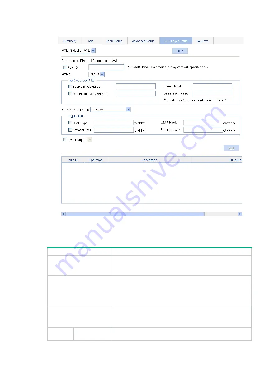
Figure 432 Configuring a rule for an Ethernet frame header ACL 


3. 

Configure a rule for an Ethernet frame header IPv4 ACL as described in 

Table 137

4. 

Click 

Add

Table 137 Configuration items 

Item


Description


ACL


Select the Ethernet frame header IPv4 ACL for which you want to 
configure rules. 
Available ACLs are Ethernet frame header IPv4 ACLs.


Rule ID


Select the 

Rule ID

 box and enter a number for the rule. 

If you do not specify the rule number, the system will assign one 
automatically. 
If the rule number you specify already exists, the following operations 
modify the configuration of the rule. 


Action


Select the action to be performed for packets matching the rule: 


Permit

—Allows matched packets to pass. 


Deny

—Drops matched packets.


MAC 
Address 

Source MAC 
Address 

Select the 

Source MAC Address

 box and enter a source MAC address 

and a mask.


Summary of Contents for FlexNetwork NJ5000

Page 1: ...HPE FlexNetwork NJ5000 5G PoE Walljack Switch User Guide Part number 5998 7332R Software version Release 1108 Document version 6W101 20161012 ...

Page 2: ...nd 12 212 Commercial Computer Software Computer Software Documentation and Technical Data for Commercial Items are licensed to the U S Government under vendor s standard commercial license Links to third party websites take you outside the Hewlett Packard Enterprise website Hewlett Packard Enterprise has no control over and is not responsible for information outside the Hewlett Packard Enterprise ...

Page 3: ...up 23 Entering the configuration wizard homepage 23 Configuring system parameters 23 Configuring management IP address 24 Finishing configuration wizard 26 Displaying system and device information 28 Displaying system information 28 Displaying basic system information 28 Displaying the system resource state 29 Displaying recent system logs 29 Setting the refresh period 29 Displaying device informa...

Page 4: ...ying a specified operation parameter for all ports 51 Displaying all the operation parameters for a port 51 Port management configuration example 52 Network requirements 52 Configuring the switch 53 Configuring port mirroring 56 Terminology 56 Mirroring source 56 Mirroring destination 56 Mirroring direction 56 Mirroring group 56 Local port mirroring 56 Configuration restrictions and guidelines 57 ...

Page 5: ... SNMP community 91 Configuring an SNMP group 92 Configuring an SNMP user 93 Configuring SNMP trap function 95 Displaying SNMP packet statistics 96 SNMPv1 v2c configuration example 97 SNMPv3 configuration example 100 Displaying interface statistics 105 Configuring VLANs 106 Overview 106 VLAN fundamentals 106 VLAN types 107 Port based VLAN 107 Restrictions and guidelines 109 Recommended VLAN configu...

Page 6: ...ies 143 Displaying and configuring MAC address entries 144 Setting the aging time of MAC address entries 145 MAC address table configuration example 145 Network requirements 145 Creating a static MAC address entry 145 Configuring MSTP 147 Overview 147 Introduction to STP 147 STP protocol packets 147 Basic concepts in STP 148 Calculation process of the STP algorithm 149 Introduction to RSTP 154 Int...

Page 7: ...ser validity check 202 ARP packet validity check 202 Configuring ARP detection 202 Configuring IGMP snooping 204 Overview 204 Basic IGMP snooping concepts 204 How IGMP snooping works 206 Protocols and standards 207 Recommended configuration procedure 207 Enabling IGMP snooping globally 208 Enabling dropping unknown multicast data globally 208 Configuring IGMP snooping in a VLAN 209 Configuring IGM...

Page 8: ...oping functions on an interface 240 Displaying clients IP to MAC bindings 240 DHCP snooping configuration example 241 Managing services 244 Overview 244 Managing services 244 Using diagnostic tools 247 Ping 247 Traceroute 247 Ping operation 248 Configuring IPv4 Ping 248 Configuring IPv6 Ping 249 Traceroute operation 249 Configuring IPv4 traceroute 249 Configuring IPv6 traceroute 250 Configuring 80...

Page 9: ...guration example 303 Configuration guidelines 307 Configuring HWTACACS 309 Recommended configuration procedure 309 Creating the HWTACACS scheme system 309 Configuring HWTACACS servers for the scheme 310 Configuring HWTACACS communication parameters for the scheme 311 HWTACACS configuration example 314 Network requirements 314 Configuring the HWTACACS server 314 Configuring the HPE NJ5000 5G PoE sw...

Page 10: ...362 Configuring secure MAC addresses 363 Configuring advanced port security control 364 Configuring permitted OUIs 366 Port security configuration examples 366 Basic port security mode configuration example 366 Advanced port security mode configuration example 369 Configuring port isolation 375 Configuring the isolation group 375 Port isolation configuration example 376 Configuring authorized IP 3...

Page 11: ...or a traffic behavior 412 Configuring other actions for a traffic behavior 413 Adding a policy 415 Configuring classifier behavior associations for the policy 415 Applying a policy to a port 416 Configuring queue scheduling on a port 417 Configuring GTS on ports 418 Configuring rate limit on a port 418 Configuring priority mapping tables 419 Configuring priority trust mode on a port 420 ACL and Qo...

Page 12: ...x Index 440 ...

Page 13: ...Windows 2000 Windows Server 2003 Enterprise Edition Windows Server 2003 Standard Edition Windows Vista Windows 7 Linux MAC OS The Windows firewall limits the number of TCP connections When the limit is reached you cannot log in to the Web interface Web browser requirements Use one of the following Web browsers to log in Internet Explorer 6 SP2 or higher Mozilla Firefox 3 or higher Google Chrome 2 ...

Page 14: ...ere the target Website resides as shown in Figure 1 Figure 1 Internet Explorer settings 1 3 Click Custom Level 4 In the Security Settings dialog box enable Run ActiveX controls and plug ins Script ActiveX controls marked safe for scripting and Active scripting ...

Page 15: ...lorer settings 2 5 Click OK to save your settings Enabling JavaScript in a Firefox browser 1 Launch the Firefox browser and select Tools Options 2 In the Options dialog box click the Content icon and select Enable JavaScript ...

Page 16: ...u log in If you click the verification code displayed on the Web login page you can obtain a new verification code The Web interface allows a maximum of 5 concurrent accesses If this limit is reached login attempts will fail A list can contain a maximum of 20000 entries if displayed in pages Logging in to the Web interface for the first time At the first login you can use the following default set...

Page 17: ...evice to a PC by using an Ethernet cable By default all interfaces belong to VLAN 1 2 Configure an IP address for the PC and make sure that the PC and device can reach each other For example assign the PC an IP address for example 169 254 1 27 within 169 254 0 0 16 except for the IP address of the device 3 Open the browser and input the login information a Type the IP address http 169 254 1 2 in t...

Page 18: ...the path of the current configuration interface in the navigation area on the right provides the Save button to quickly save the current configuration the Help button to display the Web related help information and the Logout button to log out of the Web interface Icons and buttons Table 1 describes icons and buttons you can use to configure and manage the device Table 1 Icons and buttons Icon but...

Page 19: ...ontents in pages as shown in Figure 6 You can set the number of entries displayed per page and view the contents on the first previous next and last pages or go to any page that you want to check Figure 6 Content display in pages Search function The Web interface provides basic and advanced searching functions to display entries that match specific searching criteria Basic search As shown in Figur...

Page 20: ...n in Figure 9 and then click Apply The LLDP entries with LLDP Work Mode being TxRx are displayed Figure 9 Advanced search function example 1 2 Click the Advanced Search link specify the search criteria on the advanced search page as shown in Figure 10 and then click Apply The LLDP entries with LLDP Work Mode being TxRx and LLDP Status being Disabled are displayed as shown in Figure 11 Figure 10 Ad...

Page 21: ... display the entries in a certain order On a list page you can click the name of a column header in blue to sort the entries An arrow will be displayed next to the column header you clicked as shown in Figure 12 An upward arrow indicates the ascending order and a downward arrow indicates the descending order Figure 12 Sort display ...

Page 22: ...They cannot access the device data or configure the device Monitor Users of this level can access the device data but they cannot configure the device Configure Users of this level can access device data and configure the device but they cannot perform the following tasks Upgrade the host software Add delete or modify users Back up or restore configuration files Management Users of this level can ...

Page 23: ...e synchronization status of the system clock and configure the network time Configure Syslog Loglist Display and refresh system logs Monitor Clear system logs Configure Loghost Display and configure the loghost Configure Log Setup Display and configure the buffer capacity and interval for refreshing system logs Configure Configuration Backup Back up the configuration file to be used at the next st...

Page 24: ...rrent user level to the management level Monitor Loopback Loopback Perform loopback tests on Ethernet interfaces Configure VCT VCT Check the status of the cables connected to Ethernet ports Configure Flow Interval Port Traffic Statistics Display the average rate at which the interface receives and sends packets within a specified time interval Monitor RMON Statistics Display create modify and clea...

Page 25: ...tion about an interface Configure Network menu Use Table 5 to navigate to the tasks you can perform from the Network menu Table 5 Network menu navigator Menus Tasks User level VLAN Select VLAN Select a VLAN range Monitor Create Create VLANs Configure Port Detail Display the VLAN related details of a port Monitor Detail Display the member port information about a VLAN Monitor Modify VLAN Modify the...

Page 26: ...or Port Setup Set MSTP parameters on ports Configure LLDP Port Setup Display the LLDP configuration information local information neighbor information statistics information and status information about a port Monitor Modify LLDP configuration on a port Configure Global Setup Display global LLDP configuration information Monitor Configure global LLDP parameters Configure Global Summary Display glo...

Page 27: ...4 network Use this feature only if you want to manage the switch from a different subnet than the switch Configure Remove Delete the selected IPv4 static routes Configure IPv6 Routing Summary Display the IPv6 active route table Monitor Create Create an IPv6 static route NOTE The switch does not provide Layer 3 forwarding service The IPv6 routing feature only ensures that the switch is accessible o...

Page 28: ...omain Setup Display ISP domain configuration information Monitor Add and remove ISP domains Management Authentication Display the authentication configuration information about an ISP domain Monitor Specify authentication methods for an ISP domain Management Authorization Display the authorization method configuration information about an ISP domain Monitor Specify authorization methods for an ISP...

Page 29: ...tents of the CRL Monitor Receive the CRL of a domain Configure Security menu Use Table 7 to navigate to the tasks you can perform from the Security menu Table 7 Security menu navigator Menus Tasks User level Port Isolate Group Summary Display port isolation group information Monitor Port Setup Configure the ports in an isolation group Configure Authorized IP Summary Display the configurations of a...

Page 30: ...Pv6 ACL Configure Remove Delete an IPv6 ACL or its rules Configure Queue Summary Display the queue information about a port Monitor Setup Configure a queue on a port Configure GTS Summary Display port GTS information Monitor Setup Configure port GTS Configure Line Rate Summary Display line rate configuration information Monitor Setup Configure the line rate Configure Classifier Summary Display cla...

Page 31: ... the PoE menu Table 9 QoS menu navigator Menus Tasks User level PoE Summary Display PSE information and PoE interface information Monitor PSE Setup Configure a PoE interface Configure Port Setup Configure a port Configure Features configurable from the CLI CLI provides commands for the following features Features configurable from the Web interface see Feature menu navigators for the Web interface...

Page 32: ...ent Syntax manage mode on undo manage mode on Default The HPE NJ5000 5G PoE switch operates in management mode Views System view Default command level 2 System level Usage guidelines In management mode you can assign an IP address to the device The device is manageable from the Web interface or CLI In unmanagement mode you can manage the device only from the console port Examples Enable the device...

Page 33: ...bitEthernet 1 0 3 and GigabitEthernet 1 0 4 respectively Sysname system view System View return to User View with Ctrl Z Sysname poe force power GigabitEthernet 1 0 3 1000 GigabitEthernet 1 0 4 2000 Please make sure to remove this configuration before changing your Power source Continue Y N y poe legacy enable Use poe legacy enable to enable the PD compatibility check feature Use undo poe legacy e...

Page 34: ...22 Examples Enable the PD compatibility check feature Sysname system view System View return to User View with Ctrl Z Sysname poe legacy enable ...

Page 35: ...ameters including the system name system location contact information and management IP address Basic service setup Entering the configuration wizard homepage Select Wizard from the navigation tree Figure 13 Configuration wizard homepage Configuring system parameters 1 On the wizard homepage click Next ...

Page 36: ...e system You can also set the physical location in the setup page you enter by selecting Device SNMP For more information see Configuring SNMP Syscontact Set the contact information for users to get in touch with the device vendor for help You can also set the contact information in the setup page you enter by selecting Device SNMP For more information see Configuring SNMP Configuring management I...

Page 37: ... interface and its IP address in the page that you enter by selecting Network VLAN Interface For more information see Configuring VLAN interfaces Admin status Enable or disable the VLAN interface When errors occurred in the VLAN interface disable the interface and then enable the port to bring the port to operate correctly By default the VLAN interface is down if no Ethernet ports in the VLAN is u...

Page 38: ...address Auto Configure how the VLAN interface obtains an IPv6 link local address Auto Select this option for the device to automatically generate a link local address based on the link local address prefix FE80 64 and the link layer address of the interface Manual Select this option to manually assign an IPv6 link local address to the interface Manual IPv6 address Specify an IPv6 link local addres...

Page 39: ...27 Figure 16 Configuration complete ...

Page 40: ...d description Item Description Product Information Description for the device Device Location Device location which you can configure on the page you enter by selecting Device SNMP Setup Contact Information Contact information which you can configure on the page you enter by selecting Device SNMP Setup SerialNum Serial number of the device Software Version Software version of the device Hardware V...

Page 41: ...ion see Configuring syslog Setting the refresh period To set the interval for refreshing system information select one of the following options from the Refresh Period list If you select a certain period the system refreshes system information at the specified interval If you select Manual the system refreshes system information only when you click the Refresh button Displaying device information ...

Page 42: ... information select one of the following options from the Refresh Period list If you select a certain period the system refreshes device information at the specified interval If you select Manual the system refreshes device information only when you click the Refresh button ...

Page 43: ...security purpose after the configured period Configuring system name 1 Select Device Basic from the navigation tree The system name configuration page appears Figure 19 Configuring the system name 2 Enter the system name 3 Click Apply Configuring idle timeout period 1 Select Device Basic from the navigation tree 2 Click the Web Idle Timeout tab The page for configuring idle timeout period appears ...

Page 44: ...e configuration page 2 Configure software upgrade parameters as described in Table 15 3 Click Apply Table 15 Configuration items Item Description File Specify the path and filename of the local application file which must be suffixed with the app or bin extension File Type Specify the type of the boot file for the next boot Main Boots the device Backup Boots the device when the main boot file is u...

Page 45: ...he next startup configuration file the system will check the configuration before rebooting the device If the check succeeds the system reboots the device If the check fails a dialog box appears telling you that the current configuration and the saved configuration are inconsistent and the device is not rebooted In this case save the current configuration manually before you can reboot the device ...

Page 46: ...m the navigation tree 2 Click the Diagnostic Information tab Figure 24 Diagnostic information 3 Click Create Diagnostic Information File The system begins to generate a diagnostic information file 4 Click Click to Download The File Download dialog box appears 5 Select to open this file or save this file to the local host Figure 25 The diagnostic information file is created The generation of the di...

Page 47: ... clients NTP can keep consistent timekeeping among all clock dependent devices within the network and ensure a high clock precision so that the devices can provide diverse applications based on consistent time Displaying the current system time To view the current system date and time select Device System Time from the navigation tree to enter the System Time page Figure 26 System time configurati...

Page 48: ...tus Display the synchronization status of the system clock Source Interface Set the source interface for an NTP message This configuration makes the source IP address in the NTP messages the primary IP address of this interface If the specified source interface is down the source IP address is the primary IP address of the egress interface TIP If you do not want the IP address of an interface on t...

Page 49: ...able 17 4 Click Apply Table 17 Configuration items Item Description Time Zone Set the time zone for the system Adjust clock for daylight saving time changes Adjust the system clock for daylight saving time changes which means adding one hour to the current system time Click Adjust clock for daylight saving time changes to expand the option as shown in Figure 30 You can configure the daylight savin...

Page 50: ...Network diagram Configuring the system time 1 Configure the local clock as the reference clock with the stratum of 2 Enable NTP authentication set the key ID to 24 and specify the created authentication key aNiceKey as a trusted key Details not shown 2 On Switch B configure Device A as the NTP server a Select Device System Time from the navigation tree b Click the Network Time Protocol tab c Enter...

Page 51: ...ck of a server has a stratum level higher than or equal to the level of a client s clock the client will not synchronize its clock to the server s The synchronization process takes some time The clock status might be displayed as unsynchronized after your configuration In this case refresh the page to view the clock status and system time later on If the system time of the NTP server is ahead of t...

Page 52: ... interface Log file Displaying syslogs 1 Select Device Syslog from the navigation tree The page for displaying syslogs appears You can click Reset to clear all system logs saved in the log buffer on the Web interface You can click Refresh to manually refresh the page or you can set the refresh interval on the Log Setup page to enable the system to automatically refresh the page periodically For mo...

Page 53: ...n Error Error condition Warning Warning condition Notification Normal but significant condition Information Informational message Debug Debug level message Digest Displays the brief description of the system log Description Displays the content of the system log Setting the log host 1 Select Device Syslog from the navigation tree 2 Click the Loghost tab The log host configuration page appears Figu...

Page 54: ...he Log Setup tab The syslog configuration page appears Figure 35 Syslog configuration page 3 Configure buffer capacity and refresh interval as described in Table 20 4 Click Apply Table 20 Configuration items Item Description Buffer Capacity Set the number of logs that can be stored in the log buffer Refresh Interval Set the log refresh interval You can select manual refresh or automatic refresh Ma...

Page 55: ...Configuration from the navigation tree The Backup page appears Figure 36 Backing up the configuration 2 Click the upper Backup button The file download dialog box appears 3 Choose to view the cfg file or to save the file to your local host 4 Click the lower Backup button The file download dialog box appears 5 Choose to view the xml file or to save the file to the local host Restoring the configura...

Page 56: ... configuration file that will be used at the next startup Saving the configuration takes some time Only one administrator can save the configuration at a moment If you save the configuration while the system is saving the configuration as required by another administrator the system prompts you to try again later You can save the configuration in either of the following modes Fast mode To save the...

Page 57: ...figuration Resetting the configuration restores the device s factory defaults deletes the current configuration files and reboots the device To reset the configuration 1 Select Device Configuration from the navigation tree 2 Click the Initialize tab 3 Click Restore Factory Default Settings Figure 39 Resetting the configuration ...

Page 58: ...ncluding the used space the free space and the capacity of the medium File information including all files on the medium the file sizes and the boot file types Main or Backup The boot file type is only displayed for an application file bin or app file that will be used as the main or backup boot file Downloading a file 1 Select Device File Management from the navigation tree to enter the file mana...

Page 59: ... Device File Management from the navigation tree to enter the file management page see Figure 40 2 Do one of the following Click the icon of a file to remove the file Select a file from the file list and click Remove File To remove multiple files repeat step 2 or select the files from the file list and click Remove File Specifying the main boot file 1 Select Device File Manage from the navigation ...

Page 60: ... type PVID description MDI mode flow control settings MAC learning limit and storm suppression ratios For an aggregate interface these operation parameters include its state link type PVID description and MAC learning limit Setting operation parameters for a port 1 Select Device Port Management from the navigation tree 2 Click the Setup tab Figure 41 The Setup tab 3 Set the operation parameters fo...

Page 61: ...the same PVID Description Set the description of the port MDI Set the MDI mode of the port You can use two types of Ethernet cables to connect Ethernet devices crossover cable and straight through cable To accommodate these two types of cables an Ethernet port can operate in one of the following three MDI modes across normal and auto An Ethernet port is composed of eight pins By default each pin h...

Page 62: ...riod it automatically enters low power mode When a packet arrives later the device restores power supply to the port and the port resumes its normal state Broadcast Suppression Set broadcast suppression on the port ratio Sets the maximum percentage of broadcast traffic to the total bandwidth of an Ethernet port When you select this option you must enter a percentage in the box below pps Sets the m...

Page 63: ...ported operation parameters for the port or other ports Displaying port operation parameters Displaying a specified operation parameter for all ports 1 Select Device Port Management from the navigation tree The Summary page appears by default 2 Select the option for a parameter you want to view The parameter information for all the ports is displayed in the lower part of the page Figure 42 The Sum...

Page 64: ...net 1 0 3 of the switch respectively The rates of the network adapters of these servers are all 1000 Mbps The switch connects to the external network through GigabitEthernet 1 0 4 whose speed is 1000 Mbps To avoid congestion at the egress port GigabitEthernet 1 0 4 configure the autonegotiation speed range on GigabitEthernet 1 0 1 GigabitEthernet 1 0 2 and GigabitEthernet 1 0 3 as 100 Mbps Figure ...

Page 65: ...t 1 0 4 2 Batch configure the autonegotiation speed range on GigabitEthernet 1 0 1 GigabitEthernet 1 0 2 and GigabitEthernet 1 0 3 as 100 Mbps a On the Setup tab select Auto 100 from the Speed list b Select 1 2 and 3 on the chassis front panel 1 2 and 3 represent ports GigabitEthernet 1 0 1 GigabitEthernet 1 0 2 and GigabitEthernet 1 0 3 c Click Apply ...

Page 66: ...atch configuring the port speed 3 Display the speed settings of ports a Click the Summary tab b Click the Speed button to display the speed information of all ports on the lower part of the page as shown in Figure 47 ...

Page 67: ...55 Figure 47 Displaying the speed settings of ports ...

Page 68: ...ive multiple duplicates of a packet in some cases because it can monitor multiple mirroring sources For example assume that Port 1 is monitoring bidirectional traffic on Port 2 and Port 3 on the same device If a packet travels from Port 2 to Port 3 two duplicates of the packet will be received on Port 1 Mirroring direction The mirroring direction indicates that the inbound outbound or bidirectiona...

Page 69: ... feature on the monitor port Use a monitor port only for port mirroring to make sure the data monitoring device receives and analyzes only the mirrored traffic rather than a mix of mirrored traffic and other forwarded traffic Recommended configuration procedures Step Remarks 1 Configure a local mirroring group Required For more information see Configuring a mirroring group Select the mirroring gro...

Page 70: ...bed in Table 22 4 Click Apply Table 22 Configuration items Item Description Mirroring Group ID ID of the mirroring group to be added Type Specify the type of the mirroring group to be added as Local which indicates adding a local mirroring group Configuring ports for the mirroring group 1 From the navigation tree select Device Port Mirroring 2 Click Modify Port to enter the page for configuring po...

Page 71: ... Orientation Set the direction of the traffic monitored by the monitor port of the mirroring group both Mirrors both received and sent packets on mirroring ports inbound Mirrors only packets received by mirroring port outbound Mirrors only packets sent by mirroring ports Select port s Click the ports to be configured on the chassis front panel If aggregate interfaces are configured on the device t...

Page 72: ...roups as shown in Figure 52 Figure 52 Adding a local mirroring group 3 Enter 1 for Mirroring Group ID and select Local from the Type list 4 Click Apply Configuring GigabitEthernet 1 0 1 and GigabitEthernet 1 0 2 as the source ports 1 Click Modify Port 2 Select 1 Local from the Mirroring Group ID list 3 Select Mirror Port from the Port Type list 4 Select both from the Stream Orientation list ...

Page 73: ...otification appears click Close Configuring GigabitEthernet 1 0 3 as the monitor port 1 Click Modify Port 2 Select 1 Local from the Mirroring Group ID list 3 Select Monitor Port from the Port Type list 4 Select 3 GigabitEthernet 1 0 3 on the chassis front panel Figure 54 Configuring the monitor port 5 Click Apply A configuration progress dialog box appears 6 After the success notification appears ...

Page 74: ...ss Level Select an access level for the user Users of different levels can perform different operations User levels in order from low to high are as follows Visitor A visitor level user can perform only ping and traceroute operations They cannot access the data on the device or configure the device Monitor A monitor level user can perform ping and traceroute operations and access the data on the d...

Page 75: ... not set non management level users cannot switch to the management level from a lower level To set the super password 1 Select Device Users from the navigation tree 2 Click the Super Password tab Figure 56 Setting the super password 3 Configure a super password as described in Table 25 4 Click Apply Table 25 Configuration items Item Description Create Remove Select the operation type Create Confi...

Page 76: ...sword The level switching operation does not change the access level setting for the user When the user logs in to the Web interface again the access level of the user is still the level set for the user To switch to the management level 1 Select Device Users from the navigation tree 2 Click the Switch To Management tab 3 Enter the correct super password 4 Click Login Figure 57 Switching to the ma...

Page 77: ...on guidelines When you configure a loopback test follow these restrictions and guidelines When a port is physically down you cannot perform an external loopback test on the port After a port is shut down manually you can perform neither internal nor external test on the port When a port is under loopback test you cannot apply Rate Duplex Cable Type and Port Status configuration to the port An Ethe...

Page 78: ...66 Figure 59 Loopback test result ...

Page 79: ...elect the port you want to test on the chassis front panel 3 Click Test The test result is returned within 5 seconds and displayed in the Result field Figure 60 Testing the status of the cable connected to an Ethernet port The result displays the cable status and length The cable status can be normal abnormal abnormal open abnormal short or failure When a cable is normal the cable length displayed...

Page 80: ...ecified interval Viewing port traffic statistics 1 Select Device Flow interval from the navigation tree By default the Port Traffic Statistics tab is displayed 2 View the number of packets and bytes sent and received by each port and the bandwidth use of each port over the last interval Figure 61 Port traffic statistics When the bandwidth utilization is lower than 1 1 is displayed ...

Page 81: ...nt implementations provide only four groups of MIB information alarm event history and statistics You can configure your device to collect and report traffic statistics error statistics and performance statistics RMON groups Among the RFC 2819 defined RMON groups HPE devices implement the statistics group history group event group and alarm group supported by the public MIB HPE devices also implem...

Page 82: ...ggered If the value of the monitored variable is smaller than or equal to the falling threshold a falling event is triggered The event is then handled as defined in the event group If an alarm entry crosses a threshold multiple times in succession the RMON agent generates an alarm event only for the first crossing For example if the value of a sampled alarm variable crosses the rising threshold mu...

Page 83: ...he value of the specified sampling interval is identical to that of the existing history entry the system considers their configurations are the same and the creation fails Configuring the RMON alarm function To send traps to the NMS when an alarm is triggered configure the SNMP agent as described in Configuring SNMP before configuring the RMON alarm function Perform the tasks in Table 28 to confi...

Page 84: ...ng tasks in Table 29 Table 29 Displaying RMON running status Task Remarks Displaying RMON statistics Display the interface statistics during the period from the time the statistics entry is created to the time the page is displayed The statistics are cleared after the device reboots Displaying RMON history sampling information After you create a history control entry on an interface the system cal...

Page 85: ...tem Description Interface Name Select the name of the interface on which the statistics entry is created Only one statistics entry can be created on one interface Owner Set the owner of the statistics entry Configuring a history entry 1 Select Device RMON from the navigation tree 2 Click the History tab Figure 65 History entry 3 Click Add ...

Page 86: ...f records that can be saved in the history record list If the current number of the entries in the table has reached the maximum number the system deletes the earliest entry to save the latest one The statistics include total number of received packets on the current interface total number of broadcast packets and total number of multicast packets in a sampling period Interval Set the sampling per...

Page 87: ... owner Event Type Set the actions that the system takes when the event is triggered Log The system logs the event Trap The system sends a trap in the community name of null If you select both Log and Trap the system logs the event and sends a trap If neither is selected the system takes no action Configuring an alarm entry 1 Select Device RMON from the navigation tree 2 Click the Alarm tab Figure ...

Page 88: ...a Delta sampling to obtain the variation value of the variable during the sampling interval when the sampling time is reached Owner Set the owner of the alarm entry Alarm Create Default Event Select whether to create a default event The description of the default event is default event the action is log and trap and the owner is default owner If there is no event you can create the default event A...

Page 89: ... Table 34 Field description Field Description Number of Received Bytes Total number of octets received by the interface corresponding to the MIB node etherStatsOctets Number of Received Packets Total number of packets received by the interface corresponding to the MIB node etherStatsPkts Number of Received Broadcasting Packets Total number of broadcast packets received by the interface correspondi...

Page 90: ... the interface corresponding to the MIB node etherStatsDropEvents Number of Received 64 Bytes Packets Total number of received packets with 64 octets on the interface corresponding to the MIB node etherStatsPkts64Octets Number of Received 65 to 127 Bytes Packets Total number of received packets with 65 to 127 octets on the interface corresponding to the MIB node etherStatsPkts65to127Octets Number ...

Page 91: ...ponding to the MIB node etherHistoryMulticastPkts CRCAlignErrors Number of packets received with CRC alignment errors during the sampling period corresponding to the MIB node etherHistoryCRCAlignErrors UndersizePkts Number of undersize packets received during the sampling period corresponding to the MIB node etherHistoryUndersizePkts OversizePkts Number of oversize packets received during the samp...

Page 92: ...stics table to gather statistics on GigabitEthernet 1 0 1 with the sampling interval being 10 seconds Perform corresponding configurations so that the system logs the event when the number of bytes received on the interface more than 1000 or less than 100 Figure 74 Network diagram Configuration procedure 1 Configure RMON to gather statistics for GigabitEthernet 1 0 1 a Select Device RMON from the ...

Page 93: ...shown in Figure 76 Figure 76 Displaying RMON statistics 3 Create an event to start logging after the event is triggered a Click the Event tab b Click Add The page in Figure 77 appears c Type user1 rmon in the Owner field select the box before Log and click Apply d The page displays the event entry and you can see that the entry index of the new event is 1 as shown in Figure 78 ...

Page 94: ... Click the Alarm tab b Click Add The page in Figure 79 appears c Select Number of Received Bytes from the Static Item list select GigabitEthernet1 0 1 from the Interface Name list enter 10 in the Interval field select Delta from the Simple Type list enter user1 in the Owner field enter 1000 in the Rising Threshold field select 1 from the Rising Event list enter 100 in the Falling Threshold field s...

Page 95: ...g information for event 1 on the Web interface 1 Select Device RMON from the navigation tree 2 Click the Log tab The log page appears The log in this example indicates that event 1 generated one log which was triggered because the alarm value 22050 exceeded the rising threshold 1000 The sampling type is absolute Figure 80 Log information for event 1 ...

Page 96: ...n the state of energy saving IMPORTANT Up to five energy saving policies with different time ranges can be configured on a port Specify the start time and end time in units of 5 minutes such as 08 05 to 10 15 Otherwise the start time is postponed and the end time is brought forward so that they meet the requirements For example if you set the time range to 08 08 to 10 12 the effective time range i...

Page 97: ...apable devices in the network SNMP agent Works on a managed device to receive and handle requests from the NMS and send traps to the NMS when some events such as interface state change occur Management Information Base MIB Specifies the variables for example interface status and CPU usage maintained by the SNMP agent for the SNMP manager to read and set Figure 82 Relationship between an NMS agent ...

Page 98: ...cation and privacy mechanisms to authenticate and encrypt SNMP packets for integrity authenticity and confidentiality Recommended configuration procedure SNMPv3 differs from SNMPv1 and SNMPv2c in many ways Their configuration procedures are described in separate sections Table 37 SNMPv1 or SNMPv2c configuration task list Task Remarks 1 Enabling SNMP agent Required The SNMP agent function is disabl...

Page 99: ...P user Required Before creating an SNMP user you need to create the SNMP group to which the user belongs IMPORTANT After you change the local engine ID the existing SNMPv3 users become invalid and you must re create the SNMPv3 users For more information about engine ID see Enabling SNMP agent 5 Configuring SNMP trap function Optional Allows you to configure that the agent can send SNMP traps to th...

Page 100: ... the engine ID when the user is created is not identical to the current engine ID the user is invalid Maximum Packet Size Configure the maximum size of an SNMP packet that the agent can receive or send Contact Set a character string to describe contact information for system maintenance If the device is faulty the maintainer can contact the manufacture factory according to the contact information ...

Page 101: ...k Add The Add View window appears Figure 86 Creating an SNMP view 1 4 Type the view name 5 Click Apply The page in Figure 87 appears 6 Configure the parameters as described in Table 40 7 Click Add to add the rule into the list box at the lower part of the page 8 Repeat steps 6 and 7 to add more rules for the SNMP view 9 Click Apply To cancel the view click Cancel ...

Page 102: ... OID identifies the position of a node in the MIB tree and it can uniquely identify a MIB subtree Subtree Mask Set the subtree mask a hexadecimal string Its length must be an even number in the range of 2 to 32 If no subtree mask is specified the default subtree mask all Fs will be used for mask OID matching Adding rules to an SNMP view 1 Select Device SNMP from the navigation tree 2 Click the Vie...

Page 103: ...on corresponding to the specified view on the page as shown in Figure 85 and then you can enter the page to modify the view Configuring an SNMP community 1 Select Device SNMP from the navigation tree 2 Click the Community tab The Community tab appears Figure 89 Configuring an SNMP community 3 Click Add The Add SNMP Community page appears ...

Page 104: ...me to access the agent Read and write The NMS can perform both read and write operations to the MIB objects when it uses this community name to access the agent View Specify the view associated with the community to limit the MIB objects that can be accessed by the NMS ACL Associate the community with a basic ACL to allow or prohibit the access to the agent from the NMS with the specified source I...

Page 105: ...t the read view of the SNMP group Write View Select the write view of the SNMP group If no write view is configured the NMS cannot perform the write operations to all MIB objects on the device Notify View Select the notify view the view that can send trap messages of the SNMP group If no notify view is configured the agent does not send traps to the NMS ACL Associate a basic ACL with the group to ...

Page 106: ...escribed in Table 43 5 Click Apply Table 43 Configuration items Item Description User Name Set the SNMP user name Security Level Select the security level for the SNMP group The available security levels are NoAuth NoPriv No authentication no privacy Auth NoPriv Authentication without privacy Auth Priv Authentication and privacy ...

Page 107: ...uthentication password must be the same with the authentication password Confirm Authentication Password Privacy Mode Select a privacy mode including DES56 AES128 and 3DES when the security level is Auth Priv Privacy Password Set the privacy password when the security level is Auth Priv The confirm privacy password must be the same with the privacy password Confirm Privacy Password ACL Associate a...

Page 108: ... used for receiving traps on the NMS Generally such as using IMC or MIB Browser as the NMS you can use the default port number To change this parameter to another value you need to make sure the configuration is the same with that on the NMS Security Model Select the security model for which you must set the SNMP version For the NMS to receive notifications make sure the SNMP version is the same w...

Page 109: ...e NMS at 1 1 1 2 24 uses SNMPv1 or SNMPv2c to manage the switch agent at 1 1 1 1 24 and the switch automatically sends traps to report events to the NMS Figure 98 Network diagram Configuring the agent 1 Enable SNMP a Select Device SNMP from the navigation tree The SNMP configuration page appears b Select the Enable option and select the v1 and v2c options c Click Apply ...

Page 110: ...in the Community Name field and select Read only from the Access Right list d Click Apply Figure 100 Configuring an SNMP read only community 3 Configure a read and write community a Click Add on the Community tab page The Add SNMP Community page appears b Enter private in the Community Name field and select Read and write from the Access Right list c Click Apply ...

Page 111: ...MP Trap c Click Apply Figure 102 Enabling SNMP traps 5 Configure a target host SNMP traps a Click Add on the Trap tab page The page for adding a target host of SNMP traps appears b Select the IPv4 Domain option and type 1 1 1 2 in the following field type public in the Security Name field and select v1 from the Security Model list c Click Apply ...

Page 112: ... agent The NMS can get and configure the values of some parameters on the agent through MIB nodes Disable or enable an idle interface on the agent and you can see the interface state change traps on the NMS SNMPv3 configuration example Network requirements As shown in Figure 104 the NMS 1 1 1 2 24 uses SNMPv3 to monitor and manage the interface status of the AP the agent at 1 1 1 1 24 and the AP a...

Page 113: ...he SNMP agent 2 Configure an SNMP view a Click the View tab b Click Add The page for creating an SNMP view appears c Type view1 in the View Name field d Click Apply Figure 106 Creating an SNMP view 1 e On the page that appears select the Included option type the MIB subtree OID interfaces and click Add f Click Apply A configuration progress dialog box appears g Click Close after the configuration ...

Page 114: ...ing an SNMP group 4 Configure an SNMP user a Click the User tab b Click Add The page in Figure 109 appears c Type user1 in the User Name field select Auth Priv from the Security Level list select group1 from the Group Name list select MD5 from the Authentication Mode list type authkey in the Authentication Password and Confirm Authentication Password fields select DES56 from the Privacy Mode list ...

Page 115: ...ble SNMP traps a Click the Trap tab The Trap tab page appears b Select Enable SNMP Trap c Click Apply Figure 110 Enabling SNMP traps 6 Configure a target host SNMP traps a Click Add on the Trap tab page The page for adding a target host of SNMP traps appears ...

Page 116: ...gure the NMS 1 Specify the SNMP version for the NMS as v3 2 Create an SNMP user user1 3 Enable both authentication and privacy functions 4 Use MD5 for authentication and DES56 for encryption 5 Set the authentication key to authkey and the privacy key to prikey For information about configuring the NMS see the NMS manual Verifying the configuration After the above configuration the NMS can establis...

Page 117: ...eived unicast packets InNUcastPkts Number of received non unicast packets InDiscards Number of valid packets discarded in the inbound direction InErrors Number of received invalid packets InUnknownProtos Number of received unknown protocol packets OutOctets Total octets of all packets sent through the interface OutUcastPkts Number of unicast packets sent through the interface OutNUcastPkts Number ...

Page 118: ...traffic within individual VLANs This reduces bandwidth waste and improves network performance Improving LAN security By assigning user groups to different VLANs you can isolate them at Layer 2 To enable communication between VLANs routers or Layer 3 switches are required Flexible virtual workgroup creation As users from the same workgroup can be assigned to the same VLAN regardless of their physic...

Page 119: ... any The Ethernet II encapsulation format is used in this section In addition to the Ethernet II encapsulation format Ethernet also supports other encapsulation formats including 802 2 LLC 802 2 SNAP and 802 3 raw The VLAN tag fields are added to frames encapsulated in these formats for VLAN identification When a frame carrying multiple VLAN tags passes through the device processes the frame accor...

Page 120: ... LAN in which some PCs belong to VLAN 2 and other PCs belong to VLAN 3 and Device B is uncertain about whether Device C supports VLAN tagged packets Configure on Device B the port connecting to Device C as a hybrid port to allow packets of VLAN 2 and VLAN 3 to pass through untagged Figure 116 Port link types PVID By default VLAN 1 is the PVID for all ports You can change the PVID for a port as req...

Page 121: ...ame if the frame carries the PVID tag and the port belongs to the PVID Sends the frame without removing the tag if its VLAN is carried on the port but is different from the PVID Sends the frame if its VLAN is permitted on the port The frame is sent with the VLAN tag removed or intact depending on your configuration with the port hybrid vlan command This is true of the PVID Restrictions and guideli...

Page 122: ... its PVID The three operations produce the same result and the latest operation takes effect By default the untagged VLAN of a trunk port is VLAN 1 When you change the untagged VLAN PVID of a trunk port the former untagged VLAN automatically becomes a tagged VLAN of the trunk port 4 Configure the trunk port as an untagged member of the specified VLANs a Selecting VLANs Specify the range of VLANs a...

Page 123: ...erations Configure a subset of all existing VLANs This step is required before you perform operations on the Detail Modify VLAN and Modify Port tabs b Modifying a VLAN Configure the hybrid port as an untagged member of the specified VLAN N A Required A hybrid port can have multiple untagged VLANs Repeat these steps to configure multiple untagged VLANs for a hybrid port By default the untagged VLAN...

Page 124: ...escription of the selected VLAN ID Select the ID of the VLAN whose description string is to be modified Click the ID of the VLAN to be modified in the list in the middle of the page Description Set the description string of the selected VLAN By default the description string of a VLAN is its VLAN ID such as VLAN 0001 Configuring the link type of a port You can also configure the link type of a por...

Page 125: ...f a port on the Setup tab of Device Port Management For more information see Managing ports To set the PVID for a port 1 From the navigation tree select Network VLAN 2 Click Modify Port 3 Select the port that you want to configure on the chassis front panel 4 Select the PVID option The option allows you to modify the PVID of the port 5 Set a PVID for the port By selecting the Delete box you can re...

Page 126: ... select Network VLAN The Select VLAN tab is displayed by default for you to select VLANs Figure 120 Selecting VLANs 2 Select the Display all VLANs option to display all VLANs or select the Display a subnet of all configured VLANs option to enter the VLAN IDs to be displayed 3 Click Select ...

Page 127: ...elected on the page for selecting VLANs Modify Description Modify the description string of the selected VLAN By default the description string of a VLAN is its VLAN ID such as VLAN 0001 Select membership type Set the member type of the port to be modified in the VLAN Untagged Configures the port to send the traffic of the VLAN after removing the VLAN tag Tagged Configures the port to send the tra...

Page 128: ...ports to be modified in the specified VLANs Untagged Configures the ports to send the traffic of the VLANs after removing the VLAN tags Tagged Configures the ports to send the traffic of the VLANs without removing the VLAN tags Not a Member Removes the ports from the VLANs VLAN IDs Set the IDs of the VLANs to or from which the selected ports are to be assigned or removed When you set the VLAN IDs ...

Page 129: ...thernet 1 0 1 as VLAN 100 and configure GigabitEthernet 1 0 1 to permit packets from VLAN 2 VLAN 6 through VLAN 50 and VLAN 100 to pass through Figure 123 Network diagram Configuring Switch A 1 Configure GigabitEthernet 1 0 1 as a trunk port and configure VLAN 100 as the PVID a From the navigation tree select Device Port Management b Click Setup The page for configuring ports appears c Select Trun...

Page 130: ...ernet 1 0 1 as a trunk port and its PVID as 100 2 Create VLAN 2 VLAN 6 through VLAN 50 and VLAN 100 a From the navigation tree select Network VLAN b Click Create The page for creating VLANs appears c Enter VLAN IDs 2 6 50 100 d Click Apply ...

Page 131: ...VLAN 100 as an untagged member a Click Select VLAN The page for selecting VLANs appears b Select the option before Display a subnet of all configured VLANs and enter 1 100 in the field c Click Select Figure 126 Setting a VLAN range d Click Modify VLAN The page for modifying the ports in a VLAN appears ...

Page 132: ...is complete click Close Figure 127 Assigning GigabitEthernet 1 0 1 to VLAN 100 as an untagged member 4 Assign GigabitEthernet 1 0 1 to VLAN 2 and VLAN 6 through VLAN 50 as a tagged member a Click Modify Port b Select GigabitEthernet 1 0 1 on the chassis front device panel select the Tagged option and enter VLAN IDs 2 6 50 c Click Apply A configuration progress dialog box appears d After the config...

Page 133: ...s configured Details not shown Configuration guidelines When you configure VLANs follow these guidelines As the default VLAN VLAN 1 can be neither created nor removed manually You cannot manually create or remove VLANs reserved for special purposes Dynamic VLANs cannot be removed on the page for removing VLANs You cannot remove a VLAN that has referenced a QoS policy ...

Page 134: ...e the switch The HPE NJ5000 5G PoE switch supports only one default VLAN interface for configuration management Creating a VLAN interface When you create a VLAN interface you can select to assign an IPv4 address and an IPv6 link local address to the VLAN interface in this step or in a separate step If you do not select to configure an IP address you can create the VLAN interface and configure an I...

Page 135: ...he Auto or Manual option Auto The device automatically assigns a link local address to the VLAN interface based on the link local address prefix FE80 64 and the link layer address of the VLAN interface Manual Requires manual assignment These items are available after you select the Configure IPv6 Link Local Address box Manual IPv6 Address Configure an IPv6 link local address for the VLAN interface...

Page 136: ...y selecting the Manual option In the latter case you must set the mask length or enter a mask in dotted decimal notation format BOOTP Manual Admin Status Select Up or Down from the Admin Status list to bring up or shut down the selected VLAN interface When the VLAN interface fails shut down and then bring up the VLAN interface which might restore the VLAN interface By default a VLAN interface is d...

Page 137: ...f the VLAN interface state Add IPv6 Unicast Address Assign an IPv6 site local address or global unicast address to the VLAN interface Enter an IPv6 address in the field and select a prefix length in the list next to it The prefix of the IPv6 address you entered cannot be FE80 10 the prefix of the link local address The prefix of the IPv6 site local address you enter must be FEC0 10 EUI 64 Select t...

Page 138: ...ted in the Auto mode If a manually assigned link local address is available the manually assigned one takes effect After the manually assigned link local address is removed the automatically generated one takes effect For an IPv6 VLAN interface whose IPv6 link local address is generated automatically after you assign an IPv6 site local address or global unicast address removing the IPv6 site local...

Page 139: ... shown in Table 51 for voice traffic identification Table 51 The default OUI list Number OUI Address Vendor 1 0003 6b00 0000 Cisco phone 2 00e0 7500 0000 Polycom phone An OUI address is usually the first 24 bits of a MAC address in binary format It is a globally unique identifier assigned to a vendor by the IEEE In this document however OUI addresses are used by the system to determine whether rec...

Page 140: ...narios where only IP phones access the network through the device and ports on the device transmit only voice traffic as shown in Figure 133 In this mode ports assigned to a voice VLAN transmit voice traffic exclusively which prevents the impact of data traffic on the transmission of voice traffic Figure 133 Only IP phones access the network Both modes forward tagged packets according to their tag...

Page 141: ...erent VLAN IDs for the voice VLAN the PVID of the access port and the 802 1X guest VLAN for the functions to operate normally If an IP phone sends untagged voice traffic to deliver the voice VLAN function you must configure the PVID of the access port as the voice VLAN As a result 802 1X authentication does not take effect Security mode and normal mode of voice VLANs Depending on their inbound pac...

Page 142: ...ackets The port does not check the source MAC addresses of inbound packets All types of packets can be transmitted in the voice VLAN Packets carrying the voice VLAN tag Packets carrying other tags Forwarded or dropped depending on whether the port allows packets of these VLANs to pass through Recommended voice VLAN configuration procedure Before configuring the voice VLAN you must create the VLAN ...

Page 143: ...igure up to 8 OUI addresses By default the system is configured with the two OUI addresses shown in Table 51 Configuring voice VLAN globally 1 Select Network Voice VLAN from the navigation tree 2 Click the Setup tab Figure 134 Configuring voice VLAN 3 Configure the global voice VLAN settings as described in Table 55 4 Click Apply Table 55 Configuration items Item Description Voice VLAN security Se...

Page 144: ...r Disable in the list to enable or disable the voice VLAN function on the port Voice VLAN ID Set the voice VLAN ID of a port when the voice VLAN port state is set to Enable Select Ports Select the port on the chassis front panel You can select multiple ports to configure them in bulk The numbers of the selected ports will be displayed in the Ports selected for voice VLAN field NOTE To set the voic...

Page 145: ... on a port in automatic voice VLAN assignment mode Network requirements As shown in Figure 137 Configure VLAN 2 as the voice VLAN allowing only voice traffic to pass through The IP phone connected to hybrid port GigabitEthernet 1 0 1 sends untagged voice traffic GigabitEthernet 1 0 1 operates in automatic VLAN assignment mode Set the voice VLAN aging timer to 30 minutes Configure GigabitEthernet 1...

Page 146: ...ck the Create tab c Enter VLAN ID 2 d Click Create Figure 138 Creating VLAN 2 2 Configure GigabitEthernet 1 0 1 as a hybrid port a Select Device Port Management from the navigation tree b Click the Setup tab c Select Hybrid from the Link Type list d Select GigabitEthernet 1 0 1 from the chassis front panel e Click Apply ...

Page 147: ... Select Network Voice VLAN from the navigation tree b Click the Setup tab c Select Enable in the Voice VLAN security list d Set the voice VLAN aging timer to 30 minutes e Click Apply Figure 140 Configuring the voice VLAN function globally 4 Configure voice VLAN on GigabitEthernet 1 0 1 a Click the Port Setup tab ...

Page 148: ...net 1 0 1 5 Add OUI addresses to the OUI list a Click the OUI Add tab b Enter OUI address 0011 2200 0000 c Select FFFF FF00 0000 in the Mask list d Enter description string test e Click Apply Figure 142 Adding OUI addresses to the OUI list Verifying the configuration 1 When the preceding configurations are completed the OUI Summary tab is displayed by default as shown in Figure 143 You can view th...

Page 149: ...k requirements As shown in Figure 145 Configure VLAN 2 as a voice VLAN that carries only voice traffic The IP phone connected to hybrid port GigabitEthernet 1 0 1 sends untagged voice traffic GigabitEthernet 1 0 1 operates in manual voice VLAN assignment mode and allows voice packets whose source MAC addresses match the OUI addresses specified by OUI address 0011 2200 0000 and mask ffff ff00 0000 ...

Page 150: ...ick Create Figure 146 Creating VLAN 2 2 Configure GigabitEthernet 1 0 1 as a hybrid port and configure its PVID as VLAN 2 a Select Device Port Management from the navigation tree b Click the Setup tab c Select Hybrid from the Link Type list d Select the PVID box and enter 2 in the field e Select GigabitEthernet 1 0 1 from the chassis front panel f Click Apply ...

Page 151: ... untagged member a Select Network VLAN from the navigation tree b Click the Modify Port tab c Select GigabitEthernet 1 0 1 from the chassis front panel d Select the Untagged option e Enter VLAN ID 2 f Click Apply A configuration progress dialog box appears g After the configuration process is complete click Close ...

Page 152: ...LAN from the navigation tree b Click the Port Setup tab c Select Manual in the Voice VLAN port mode list d Select Enable in the Voice VLAN port state list e Enter 2 in the VLAN IDs field f Select GigabitEthernet 1 0 1 on the chassis front panel g Click Apply Figure 149 Configuring voice VLAN on GigabitEthernet 1 0 1 5 Add OUI addresses to the OUI list ...

Page 153: ... addresses to the OUI list Verifying the configuration 1 When the preceding configurations are complete the OUI Summary tab is displayed by default as shown in Figure 151 You can view the information about the newly added OUI address Figure 151 Displaying the current OUI list of the device 2 Click the Summary tab where you can view the current voice VLAN information ...

Page 154: ... a VLAN functioning as a voice VLAN disable its voice VLAN function first Only one VLAN is supported and only an existing static VLAN can be configured as the voice VLAN Do not enable the voice VLAN function on a link aggregation group member port After you assign a port operating in manual voice VLAN assignment mode to the voice VLAN the voice VLAN takes effect ...

Page 155: ...ies the source MAC address for example MAC SOURCE of the frame 2 Looks up the source MAC address in the MAC address table If an entry is found the device updates the entry If no entry is found the device adds an entry for MAC SOURCE and Port A 3 When the device receives a frame destined for MAC SOURCE after learning this source MAC address the device finds the MAC SOURCE entry in the MAC address t...

Page 156: ...ck Add in the bottom to enter the page for creating MAC address entries Figure 154 Creating a MAC address entry 3 Configure a MAC address entry as described in Table 58 4 Click Apply Table 58 Configuration items Item Description MAC Set the MAC address to be added Type Set the type of the MAC address entry Static Static MAC address entries that never age out Dynamic Dynamic MAC address entries tha...

Page 157: ...ms Item Description No aging Specify that the MAC address entry never ages out Aging time Set the aging time for the MAC address entry MAC address table configuration example Network requirements Use the Web based NMS to configure the MAC address table of the device Add a static MAC address 00e0 fc35 dc71 under GigabitEthernet 1 0 1 in VLAN 1 Creating a static MAC address entry 1 Select Network MA...

Page 158: ...146 Figure 156 Creating a static MAC address entry ...

Page 159: ...g tree protocol packets STP enabled network devices exchange BPDUs to establish a spanning tree BPDUs contain sufficient information for the network devices to complete spanning tree calculation STP uses the following types of BPDUs Configuration BPDUs Used for calculating a spanning tree and maintaining the spanning tree topology Topology change notification TCN BPDUs Used for notifying the conce...

Page 160: ...e has only one root port The root bridge has no root port Designated bridge and designated port Classification Designated bridge Designated port For a device Device directly connected with the local device and responsible for forwarding BPDUs to the local device Port through which the designated bridge forwards BPDUs to the local device For a LAN Device responsible for forwarding BPDUs to this LAN...

Page 161: ...figuration BPDU as the root port Table 60 describes how the optimum configuration BPDU is selected 2 Based on the configuration BPDU and the path cost of the root port the device calculates a designated port configuration BPDU for each of the other ports The root bridge ID is replaced with that of the configuration BPDU of the root port The root path cost is replaced with that of the configuration...

Page 162: ...same root bridge ID their root path costs are compared For example the root path cost in a configuration BPDU plus the path cost of a receiving port is S The configuration BPDU with the smallest S value has the highest priority c If all configuration BPDUs have the same root bridge ID and S value their designated bridge IDs designated port IDs and the IDs of the receiving ports are compared in seq...

Page 163: ...root bridge It does not make any change to the configuration BPDU of each port and it starts sending out configuration BPDUs periodically AP1 0 0 0 AP1 AP2 0 0 0 AP2 Device B Port BP1 receives the configuration BPDU of Device A 0 0 0 AP1 Device B finds that the received configuration BPDU is superior to the configuration BPDU of the local port 1 0 1 BP1 and it updates the configuration BPDU of BP1...

Page 164: ... Root port CP1 0 0 0 AP2 Designated port CP2 0 10 2 CP2 Then port CP2 receives the updated configuration BPDU of Device B 0 5 1 BP2 Because the received configuration BPDU is superior to its own configuration BPDU Device C launches a BPDU update process At the same time port CP1 receives periodic configuration BPDUs from Device A Device C does not launch an update process after comparison CP1 0 0 ...

Page 165: ...ess to establish a new path to restore the network connectivity However the newly calculated configuration BPDU cannot be propagated throughout the network immediately so the old root ports and designated ports that have not detected the topology change continue forwarding data along the old path If the new root ports and designated ports begin to forward data as soon as they are elected a tempora...

Page 166: ... it connects to a point to point link or is an edge port RSTP limitations Although RSTP enables faster network convergence than STP RSTP fails to provide load balancing among VLANs As with STP all RSTP bridges in a LAN share one spanning tree and forward packets from all VLANs along this spanning tree MSTP features Developed based on IEEE 802 1s MSTP overcomes the limitations of STP and RSTP In ad...

Page 167: ...ultiple MST regions can exist in a switched network You can assign multiple devices to the same MST region In Figure 160 the switched network comprises four MST regions MST region A0 through MST region D0 and all devices in each MST region have the same MST region configuration MSTI MSTP can generate multiple independent spanning trees in an MST region and each spanning tree is mapped to a range o...

Page 168: ...ion CIST The common and internal spanning tree CIST is a single spanning tree that connects all devices in a switched network It consists of the ISTs in all MST regions and the CST In Figure 160 the ISTs in all MST regions plus the inter region CST constitute the CIST of the entire network Regional root bridge The root bridge of the IST or an MSTI within an MST region is the regional root bridge o...

Page 169: ...the same spanning tree device are connected so the device blocks one of the ports The blocked port acts as the backup Boundary port Connects an MST region to another MST region or to an STP RSTP running device In MSTP calculation a boundary port s role on an MSTI is consistent with its role on the CIST But that is not true with master ports A master port on MSTIs is a root port on the CIST Port st...

Page 170: ...rates a CST among these MST regions through calculation The CST and ISTs constitute the CIST of the entire network MSTI calculation Within an MST region MSTP generates different MSTIs for different VLANs based on the VLAN to instance mappings For each spanning tree MSTP performs a separate calculation process which is similar to spanning tree calculation in STP RSTP For more information see Calcul...

Page 171: ...nects to a user terminal configure it as an edge port and enable BPDU guard for it This enables the port to quickly transit to the forwarding state when ensuring network security Recommended MSTP configuration procedure Step Remarks 1 Configuring an MST region Optional Configure the MST region related parameters and VLAN to instance mappings By default the MST region related parameters adopt the d...

Page 172: ... region name is the bridge MAC address of the device by default Revision Level Revision level of the MST region Manual Instance ID and VLAN ID Manually add VLAN to instance mappings Click Apply to add the VLAN to instance mapping entries to the list Modulo The device automatically maps 4094 VLANs to the corresponding MSTIs based on the modulo value 4 Click Activate Configuring MSTP globally 1 From...

Page 173: ...P globally BPDU Guard Selects whether to enable BPDU guard BPDU guard can protect the device from malicious BPDU attacks making the network topology stable Mode Sets the operating mode of STP STP Each port on a device sends out STP BPDUs RSTP Each port on a device sends out RSTP BPDUs and automatically migrates to STP compatible mode when detecting that it is connected with a device running STP MS...

Page 174: ... meet a certain formula Otherwise the network topology will not be stable Hewlett Packard Enterprise recommends you to set the network diameter and then have the device automatically calculate the forward delay hello time and max age The bridge diameter cannot be configured together with the timers Instance Instance ID Root Type and Bridge Priority Sets the role of the device in the MSTI or the br...

Page 175: ...ort can be elected as the root port of a device If all other conditions are the same the port with the highest priority will be elected as the root port On an MSTP enabled device a port can have different priorities in different MSTIs and the same port can play different roles in different MSTIs so that data of different VLANs can be propagated along different physical paths implementing per VLAN ...

Page 176: ... want to configure MSTP on the chassis front panel If aggregate interfaces are configured on the device the page displays a list of aggregate interfaces below the chassis front panel You can select aggregate interfaces from this list Table 67 Protection types Protection type Description Edged Port Sets the port as an edge port Some ports of access layer devices are directly connected to PCs or fil...

Page 177: ...RNING The port is in learning state so the port learns MAC addresses but does not forward user traffic DISCARDING The port is in discarding state so the port does not learn MAC addresses or forward user traffic DOWN The port is down Port Protocol Whether STP is enabled on the port Port Role Role of the port which can be Alternate Backup Root Designated Master or Disabled Port Priority Priority of ...

Page 178: ... to the forwarding state Num of Vlans Mapped Number of VLANs mapped to the current MSTI PortTimes Major parameters for the port Hello Hello timer MaxAge Max Age timer FWDly Forward delay timer MsgAge Message Age timer Remain Hop Remaining hops BPDU Sent Statistics on sent BPDUs BPDU Received Statistics on received BPDUs Protocol Status Whether MSTP is enabled Protocol Std MSTP standard Version MST...

Page 179: ...TI 3 is Switch C Figure 167 Network diagram Permit next to a link in the figure is followed by the VLANs the packets of which are permitted to pass this link Configuration procedure Configuring Switch A 1 Configure an MST region a From the navigation tree select Network MSTP By default the Region tab is displayed b Click Modify Figure 168 The region tab c Set the region name to example d Set the r...

Page 180: ...AN to instance mapping entries to the VLAN to instance mapping list j Click Activate Figure 169 Configuring an MST region 2 Configure MSTP globally a From the navigation tree select Network MSTP b Click the Global tab c Select Enable from the Enable STP Globally list d Select MSTP from the Mode list e Select the box before Instance f Set the Instance ID field to 1 g Set the Root Type field to Prim...

Page 181: ...bally a From the navigation tree select Network MSTP b Click the Global tab c Select Enable from the Enable STP Globally list d Select MSTP from the Mode list e Select the box before Instance f Set the Instance ID field to 2 g Set the Root Type field to Primary h Click Apply Configuring Switch C 1 Configure an MST region on the switch in the same way the MST region is configured on Switch A ...

Page 182: ...re Instance f Set the Instance ID field to 3 g Set the Root Type field to Primary h Click Apply Configuring Switch D 1 Configure an MST region on the switch in the same way the MST region is configured on Switch A 2 Configure MSTP globally a From the navigation tree select Network MSTP b Click Global c Select Enable from the Enable STP Globally list d Select MSTP from the Mode list e Click Apply ...

Page 183: ...171 Figure 171 Configuring MSTP globally on Switch D ...

Page 184: ...Us from the LLDP neighbors in a standard MIB LLDP enables a network management system to quickly detect and identify Layer 2 network topology changes For more information about MIBs see Configuring SNMP Basic concepts LLDP frame formats LLDP sends device information in LLDP frames LLDP frames are encapsulated in Ethernet II or SNAP frames LLDP frames encapsulated in Ethernet II Figure 172 LLDP fra...

Page 185: ...le TLVs Each TLV carries a type of device information as shown in Figure 174 Figure 174 LLDPDU encapsulation format An LLDPDU can carry up to 28 types of TLVs Mandatory TLVs include Chassis ID TLV Port ID TLV Time to Live TLV and End of LLDPDU TLV Other TLVs are optional TLVs A TLV is an information element that contains the type length and value fields LLDPDU TLVs include the following categories...

Page 186: ...management address used to reach higher level entities to assist discovery by network management The interface number and OID associated with the address IEEE 802 1 organizationally specific TLVs Table 72 IEEE 802 1 organizationally specific TLVs Type Description Port VLAN ID Specifies the port s VLAN identifier PVID An LLDPDU carries only one TLV of this type Port And Protocol VLAN ID Indicates w...

Page 187: ...d easy to use solution for deploying voice devices in Ethernet LLDP MED TLVs are shown in Table 74 Table 74 LLDP MED TLVs Type Description LLDP MED Capabilities Allows a network device to advertise the LLDP MED TLVs that it supports Network Policy Allows a network device or terminal device to advertise the VLAN ID of the specific port the VLAN type and the Layer 2 and Layer 3 priorities for specif...

Page 188: ...de sends LLDP frames to its directly connected devices both periodically and when the local configuration changes To prevent LLDP frames from overwhelming the network during times of frequent changes to local device information an interval is introduced between two successive LLDP frames This interval is shortened to 1 second in either of the following cases A new neighbor is discovered A new LLDP...

Page 189: ...To enable LLDP to work on a port enable LLDP both globally and on the port 4 Displaying LLDP information for a port Optional You can display the local LLDP information neighbor information statistics and status information of a port where The local LLDP information refers to the TLVs to be advertised by the local device to neighbors The neighbor information refers to the TLVs received from neighbo...

Page 190: ...ingle port or for multiple ports in batch Setting LLDP parameters for a single port 1 From the navigation tree select Network LLDP By default the Port Setup tab is displayed 2 Click the icon for the port On the page as shown in Figure 176 the LLDP settings of the port are displayed Figure 176 Modifying LLDP settings on a port ...

Page 191: ...s CDP frames TxRx Sends and receives CDP frames To enable LLDP to be compatible with CDP on the port you must enable CDP compatibility on the Global Setup tab and set the CDP operating mode on the port to TxRx LLDP Polling Interval Enable LLDP polling and set the polling interval If no polling interval is set LLDP polling is disabled With the polling mechanism LLDP periodically detects local confi...

Page 192: ...itted LLDP frames Inventory Select the box to include the hardware revision TLV firmware revision TLV software revision TLV serial number TLV manufacturer name TLV model name TLV and asset ID TLV in transmitted LLDP frames Network Policy Select the box to include the network policy TLV in transmitted LLDP frames Extended Power via MDI Capability Select the box to include the extended power via MDI...

Page 193: ...Figure 177 Modifying LLDP settings on ports in batch 4 Set the LLDP settings for these ports as described in Table 75 5 Click Apply A progress dialog box appears 6 Click Close on the progress dialog box when the progress dialog box prompts that the configuration succeeds Configuring LLDP globally 1 From the navigation tree select Network LLDP 2 Click the Global Setup tab ...

Page 194: ...he TTL multiplier and the LLDP frame transmission interval is less than 255 seconds for CDP compatible LLDP to work correctly with Cisco IP phones Fast LLDPDU Count Set the number of LLDP frames sent each time fast LLDP frame transmission is triggered TTL Multiplier Set the TTL multiplier The TTL TLV carried in an LLDPDU determines how long the device information carried in the LLDPDU can be saved...

Page 195: ...local configuration changes To avoid excessive number of LLDP frames caused by frequent local configuration changes an LLDP frame transmission delay is introduced After sending an LLDP frame the port must wait for the specified interval before it can send another one LLDP frame transmission delay must be less than the TTL to make sure the LLDP neighbors can receive LLDP frames to update informatio...

Page 196: ... Power class of the PD Unknown Class0 Class1 Class2 Class3 Class4 Media policy type Media policy type Unknown Voice Voice signaling Guest voice Guest voice signaling Soft phone voice Videoconferencing Streaming video Video signaling PoE PSE power source PSE power source type Primary Backup Port PSE priority PoE power supply priority of PSE ports Unknown Unknown PSE priority Critical Priority level...

Page 197: ...s Interface name Agent circuit ID Locally assigned Locally defined port ID type other than those listed above Port ID Port ID value System capabilities supported Capabilities supported on the system Repeater Bridge Router System capabilities enabled Capabilities enabled on the system Repeater Bridge Router Auto negotiation supported Indicates whether autonegotiation is supported on the port Auto n...

Page 198: ... Media policy type Media policy type Unknown Voice Voice signaling Guest voice Guest voice signaling Soft phone voice Videoconferencing Streaming video Video signaling Unknown Policy Indicates whether the media policy type is unknown VLAN tagged Indicates whether packets of the media VLAN are tagged Media policy VlanID ID of the media VLAN Media policy L2 priority Layer 2 priority Media policy Dsc...

Page 199: ...tistic information tab 5 Click the Status Information tab to display the LLDP status information Figure 182 The status information tab Displaying global LLDP information 1 From the navigation tree select Network LLDP 2 Click the Global Summary tab to display global local LLDP information and statistics Table 79 describes the fields ...

Page 200: ...s that require the discovery service of LLDP belong to this category Class II A media endpoint device The class II endpoint devices support the media stream capabilities and the capabilities of generic endpoint devices Class III A communication endpoint device The class III endpoint devices directly support end users of the IP communication system Providing all capabilities of generic and media en...

Page 201: ...185 Network diagram Configuring Switch A 1 Optional Enable LLDP on GigabitEthernet 1 0 1 and GigabitEthernet 1 0 2 By default LLDP is enabled on Ethernet ports 2 Set the LLDP operating mode to Rx on GigabitEthernet 1 0 1 and GigabitEthernet 1 0 2 a From the navigation tree select Network LLDP By default the Port Setup tab is displayed as shown in Figure 186 b Select port GigabitEthernet1 0 1 and G...

Page 202: ...appears 4 Click Close on the progress dialog box when the progress dialog box prompts that the configuration succeeds Figure 187 Setting LLDP on multiple ports 5 Enable global LLDP a Click the Global Setup tab as shown in Figure 188 b Select Enable from the LLDP Enable list 6 Click Apply A progress dialog box appears ...

Page 203: ...LLDP is enabled on Ethernet ports 2 Set the LLDP operating mode to Tx on GigabitEthernet 1 0 1 a From the navigation tree select Network LLDP By default the Port Setup tab is displayed b Click the icon for port GigabitEthernet 1 0 1 c Select Tx from the LLDP Operating Mode list 3 Click Apply A progress dialog box appears 4 Click Close on the progress dialog box when the progress dialog box prompts...

Page 204: ...abitEthernet 1 0 1 on Switch A a From the navigation tree select Network LLDP By default the Port Setup tab is displayed b Click the GigabitEthernet1 0 1 port name in the port list c Click the Status Information tab at the lower half of the page The output shows that port GigabitEthernet 1 0 1 is connected to an MED neighbor device Figure 190 The status information tab 1 2 Display the status infor...

Page 205: ... configuration guidelines When you configure LLDP follow these guidelines To make LLDP take effect on a port enable LLDP both globally and on the port To advertise LLDP MED TLVs other than the LLDP MED capabilities TLV include the LLDP MED capabilities TLV To remove the LLDP MED capabilities TLV remove all other LLDP MED TLVs To remove the MAC PHY configuration TLV remove the LLDP MED capabilities...

Page 206: ...value 2 represents an ARP reply Sender hardware address Hardware address of the device sending the message Sender protocol address Protocol address of the device sending the message Target hardware address Hardware address of the device to which the message is being sent Target protocol address Protocol address of the device to which the message is being sent ARP operating mechanism As shown in Fi...

Page 207: ...way responds with its MAC address in an ARP reply to Host A 3 Host A uses the gateway s MAC address to encapsulate the packet and then sends the packet to the gateway 4 If the gateway has an ARP entry for Host B it forwards the packet to Host B directly If not the gateway broadcasts an ARP request in which the target IP address is the IP address of Host B 5 After the gateway gets the MAC address o...

Page 208: ...C address change Gratuitous ARP packet learning This feature enables a device to create or update ARP entries by using the sender IP and MAC addresses in received gratuitous ARP packets When this feature is disabled the device uses the received gratuitous ARP packets to update existing ARP entries only Configuring ARP entries Displaying ARP entries From the navigation tree select Network ARP Manag...

Page 209: ...e port must belong to the VLAN The corresponding VLAN interface must have been created Port Removing ARP entries 1 From the navigation tree select Network ARP Management The default ARP Table page appears as shown in Figure 195 2 Remove ARP entries To remove specific ARP entries select the boxes of target ARP entries and click Del Selected To remove all static and dynamic ARP entries click Delete ...

Page 210: ...segment Enable the device to send gratuitous ARP packets upon receiving ARP requests from another network segment By default the device does not send gratuitous ARP packets upon receiving ARP requests from another network segment Static ARP configuration example Network Requirements As shown in Figure 198 hosts are connected to Switch A and Switch A is connected to Router B through GigabitEthernet...

Page 211: ...g VLAN 100 2 Add GigabitEthernet 1 0 1 to VLAN 100 a Click the Modify Port tab b In the Select Ports area select interface GigabitEthernet 1 0 1 c Select Untagged for Select membership type d Enter 100 in the VLAN IDs field e Click Apply A configuration process dialog box appears f After the configuration process is complete click Close ...

Page 212: ...0 a From the navigation tree select Network VLAN Interface b Click the Create tab c Enter 100 in the VLAN ID field d Select Configure Primary IPv4 Address e Select Manual f Enter 192 168 1 2 in the IPv4 Address field g Enter 24 or 255 255 255 0 in the Mask Length field h Click Apply ...

Page 213: ...ARP Management The default ARP Table page appears b Click Add c Enter 192 168 1 1 in the IP Address field d Enter 00e0 fc01 0000 in the MAC Address field e Select Advanced Options f Enter 100 in the VLAN ID field g Select GigabitEthernet1 0 1 from the Port list h Click Apply Figure 202 Creating a static ARP entry ...

Page 214: ...This feature does not check ARP packets received from ARP trusted ports It checks ARP packets received from ARP untrusted ports based on the following objects src mac Checks whether the sender MAC address in the message body is identical to the source MAC address in the Ethernet header If they are identical the packet is forwarded Otherwise the packet is discarded dst mac Checks the target MAC add...

Page 215: ...ck the button To remove ports from the Trusted Ports list select one or multiple ports from the list and click the button ARP Packet Validity Check Select ARP packet validity check modes Discard the ARP packet whose sender MAC address is different from the source MAC address in the Ethernet header Discard the ARP packet whose target MAC address is all 0s all 1s or inconsistent with the destination...

Page 216: ...s not enabled the Layer 2 switch floods multicast packets to all hosts When IGMP snooping is enabled the Layer 2 switch forwards multicast packets of known multicast groups to only the receivers of the multicast groups Figure 204 Multicast forwarding before and after IGMP snooping is enabled Basic IGMP snooping concepts This section lists the basic IGMP snooping concepts IGMP snooping related port...

Page 217: ...ember ports in this document include both dynamic and static ports NOTE When IGMP snooping is enabled all ports that receive PIM hello messages or IGMP general queries with the source addresses other than 0 0 0 0 are considered dynamic router ports Aging timers for dynamic ports in IGMP snooping Timer Description Message received before the timer expires Action after the timer expires Dynamic rout...

Page 218: ...tch forwards it through all the router ports in the VLAN resolves the address of the reported multicast group and performs one of the following actions If no forwarding entry matches the group address the switch creates a forwarding entry for the group adds the receiving port as a dynamic member port to the forwarding entry and starts an aging timer for the port If a forwarding entry matches the g...

Page 219: ... If the port assuming that it is a dynamic member port receives an IGMP report in response to the group specific query before its aging timer expires it means that some host attached to the port is receiving or expecting to receive multicast data for the multicast group The switch restarts the aging timer for the port If the port receives no IGMP report in response to the group specific query befo...

Page 220: ...uidelines Before you enable IGMP snooping on a port enable multicast routing or IGMP snooping globally IGMP snooping enabled on a port takes effect only after IGMP snooping is enabled in the VLAN or IGMP is enabled on the VLAN interface 5 Displaying IGMP snooping multicast forwarding entries Optional Enabling IGMP snooping globally 1 From the navigation tree select Network IGMP snooping 2 Click En...

Page 221: ...nooping in a VLAN 3 Configure the parameters as described in Table 83 4 Click Apply Table 83 Configuration items Item Description IGMP snooping Enable or disable IGMP snooping in the VLAN You can proceed with the subsequent configurations only if Enable is selected here Version The default setting is IGMPv2 By configuring an IGMP snooping version you actually configure the versions of IGMP message...

Page 222: ...c forwarding at the network layer On a network without Layer 3 multicast devices IGMP querier cannot work because a Layer 2 device does not support IGMP To address this issue you can enable IGMP snooping querier on a Layer 2 device so that the device can generate and maintain multicast forwarding entries at the data link layer providing IGMP querier functions Query interval Configure the IGMP quer...

Page 223: ...er of multicast groups on a port exceeds the limit that you are setting the system removes all the forwarding entries related to that port from the IGMP snooping forwarding table The receiver hosts attached to that port can join multicast groups again before the number of multicast groups on the port reaches the limit Fast Leave Enable or disable fast leave processing on the port When a port that ...

Page 224: ...ress Router Port s All router ports Member Port s All member ports IGMP snooping configuration example Network requirements As shown in Figure 212 IGMPv2 runs on Router A and IGMPv2 snooping runs on Switch A Router A acts as the IGMP querier Perform the configuration so Host A can receive the multicast data addressed to the multicast group 224 1 1 1 Figure 212 Network diagram Source Router A Switc...

Page 225: ... the navigation tree select Network VLAN b Click the Create tab c Enter 100 as the VLAN ID d Click Apply Figure 213 Creating VLAN 100 2 Assign GigabitEthernet 1 0 1 through GigabitEthernet 1 0 3 to VLAN 100 a Click the Modify Port tab b Select GigabitEthernet 1 0 1 GigabitEthernet 1 0 2 and GigabitEthernet 1 0 3 in the Select Ports area c Select Untagged for Select membership type d Enter 100 as t...

Page 226: ...bally a From the navigation tree select Network IGMP snooping b Select Enable c Click Apply Figure 215 Enabling IGMP snooping and dropping unknown multicast data globally 4 Enable IGMP snooping for VLAN 100 a Click the icon for VLAN 100 b Select Enable for IGMP snooping c Select 2 for Version d Click Apply ...

Page 227: ...on about IGMP snooping multicast forwarding entries Figure 217 Displaying IGMP snooping multicast forwarding entries 3 Click the icon for the multicast entry 0 0 0 0 224 1 1 1 to display detailed information about this entry Figure 218 Displaying detailed information about the entry The output shows that GigabitEthernet 1 0 3 of Switch A is listening to the multicast streams destined for multicast...

Page 228: ...enabled the Layer 2 switch floods IPv6 multicast packets to all hosts When MLD snooping is enabled the Layer 2 switch forwards multicast packets of known IPv6 multicast groups to only the receivers of the multicast groups Figure 219 IPv6 multicast forwarding before and after MLD snooping is enabled Basic MLD snooping concepts This section lists the basic MLD snooping concepts MLD snooping related ...

Page 229: ...ied router ports and member ports in this document include both dynamic and static ports NOTE When MLD snooping is enabled all ports that receive IPv6 PIM hello messages or MLD general queries with source addresses other than 0 0 are considered dynamic router ports Aging timers for dynamic ports in MLD snooping Timer Description Message received before the timer expires Action after the timer expi...

Page 230: ... IPv6 multicast group membership After receiving an MLD report the switch forwards it through all the router ports in the VLAN and resolves the address of the reported IPv6 multicast group The switch also performs one of the following actions If no forwarding entry matches the IPv6 group address the switch creates a forwarding entry for the group adds the receiving port as a dynamic member port to...

Page 231: ...t it is a dynamic member port receives any MLD report in response to the MLD multicast address specific query before its aging timer expires it means that some host attached to the port is receiving or expecting to receive IPv6 multicast data for that IPv6 multicast group The switch resets the aging timer for the port If the port receives no MLD report in response to the MLD multicast address spec...

Page 232: ...ups and fast leave processing on a port of the specified VLAN When you configure MLD snooping port functions follow these guidelines Enable MLD snooping globally before you enable it on a port MLD snooping enabled on a port takes effect only after MLD snooping is enabled for the VLAN 5 Displaying MLD snooping multicast forwarding entries Optional Enabling MLD snooping globally 1 Select Network MLD...

Page 233: ...cribed in Table 86 4 Click Apply Table 86 Configuration items Item Description MLD snooping Enable or disable MLD snooping in the VLAN You can proceed with the subsequent configurations only if Enable is selected here Version The default setting is MLDv1 By configuring an MLD snooping version you actually configure the versions of MLD messages that MLD snooping can process MLDv1 snooping can proce...

Page 234: ... 2 device so that the device can generate and maintain IPv6 multicast forwarding entries at data link layer providing MLD querier functions Query interval Configure the MLD general query interval General Query Source Address Specify the source IPv6 address of MLD general queries Special Query Source Address Specify the source IPv6 address of MLD multicast address specific queries Configuring MLD s...

Page 235: ... that port from the MLD snooping forwarding table The receiver hosts to that port can join the IPv6 multicast groups again before the number of IPv6 multicast groups on this port reaches the limit Fast Leave Enable or disable fast leave processing on the port When a port that is enabled with the MLD snooping fast leave processing feature receives an MLD done message the switch immediately deletes ...

Page 236: ...ter Ports All router ports Member Ports All member ports MLD snooping configuration example Network requirements As shown in Figure 227 MLDv1 runs on Router A and MLDv1 snooping runs on Switch A Router A acts as the MLD querier Perform the configuration so that Host A can receive the IPv6 multicast packets destined for the IPv6 multicast group FF1E 101 Figure 227 Network diagram Source Router A Sw...

Page 237: ...ate VLAN 100 a Select Network VLAN from the navigation tree b Click the Create tab c Enter 100 as the VLAN ID d Click Apply Figure 228 Creating VLAN 100 2 Assign GigabitEthernet 1 0 1 through GigabitEthernet 1 0 3 to VLAN 100 a Click the Modify Port tab b Select GigabitEthernet 1 0 1 GigabitEthernet 1 0 2 and GigabitEthernet 1 0 3 in the Select Ports area c Select Untagged for Select membership ty...

Page 238: ...data globally a Select Network MLD snooping from the navigation tree b Select Enable c Click Apply Figure 230 Enabling MLD snooping and dropping unknown IPv6 multicast data globally 4 Enable MLD snooping a Click the icon for VLAN 100 b Select Enable for MLD snooping c Select 1 for Version d Click Apply ...

Page 239: ...ation about MLD snooping multicast forwarding entries Figure 232 Displaying MLD snooping multicast forwarding entries 3 Click the icon for the multicast entry FF1E 101 to display detailed information about this entry Figure 233 Displaying detailed information about the entry The output shows that GigabitEthernet 1 0 3 of Switch A is listening to multicast streams destined for IPv6 multicast group ...

Page 240: ... You do not need to configure routes in any other situations including The configuration terminal is on the same subnet as the switch In this situation a direct route is automatically created on the switch after you assign an IP address to the VLAN interface The configuration terminal is on a different subnet than the switch but a gateway address is assigned to the switch through DHCP In this situ...

Page 241: ...ve only one IPv4 static route to one destination Next Hop Enter the next hop IP address in dotted decimal notation Interface Select the management VLAN interface as the outgoing interface NOTE To remove a route access the Remove tab Displaying the IPv4 active route table Select Network IPv4 Routing from the navigation tree The Summary tab displays the IPv4 routing table The IPv4 routing table cont...

Page 242: ...eference value for the static route This setting is for route selection among multiple routes to the same destination You can use the default setting because you can have only one IPv6 static route to one destination Next Hop Enter the next hop address in the same format as the destination IP address Interface Select the management VLAN interface as the outgoing interface NOTE To remove a route ac...

Page 243: ...231 Figure 237 IPv6 active route table ...

Page 244: ...t configuration see Configuring VLAN interfaces Figure 238 A typical DHCP application DHCP address allocation Allocation mechanisms DHCP supports the following mechanisms for IP address allocation Static allocation The network administrator assigns an IP address to a client for example a WWW server and DHCP conveys the assigned address to the client Automatic allocation DHCP assigns a permanent IP...

Page 245: ... the DHCP ACK message it broadcasts a gratuitous ARP packet to verify whether the IP address assigned by the server is in use If the client receives no response within the specified time the client uses this IP address Otherwise the client sends a DHCP DECLINE message to the server and requests an IP address again IP address lease extension A dynamically assigned IP address has a lease When the le...

Page 246: ...dr Client IP address if the client has an IP address that is valid and usable Otherwise it is set to zero The client does not use this field to request a specific IP address to lease yiaddr Your client IP address assigned by the server siaddr Server IP address from which the client obtained configuration parameters giaddr Gateway IP address of the first relay agent a request message traveled chadd...

Page 247: ...e option It specifies a list of classless static routes the destination addresses in these static routes are classless that the requesting client should add to its routing table If both Option 33 and Option 121 exist Option 33 is ignored Option 150 TFTP server IP address option It specifies the TFTP server IP address to be assigned to the client For more information about DHCP options see RFC 2132...

Page 248: ...C address of the DHCP snooping device that received the client s request The following figure gives its format The value of the sub option type is 2 and that of the remote ID type is 0 Figure 243 Sub option 2 in normal padding format Protocols and standards RFC 2131 Dynamic Host Configuration Protocol RFC 2132 DHCP Options and BOOTP Vendor Extensions RFC 1542 Clarifications and Extensions for the ...

Page 249: ...ncludes the MAC and IP addresses of a client the port that connects to the DHCP client and the VLAN The DHCP snooping entries can be used by ARP detection to prevent ARP attacks For more information about ARP detection see Configuring ARP attack protection Application of trusted ports Configure ports facing the DHCP server as trusted ports and configure other ports as untrusted ports As shown in F...

Page 250: ...bout the DHCP client so the administrator can locate the DHCP client for security and accounting purposes For more information see Option 82 DHCP snooping uses the strategies shown in Table 92 to handle Option 82 for DHCP request messages If a response returned by the DHCP server contains Option 82 DHCP snooping removes Option 82 before forwarding the response to the client If the response contain...

Page 251: ...pecify the ports connected to the authorized DHCP servers as trusted to make sure DHCP clients can obtain valid IP addresses The trusted port and the port connected to the DHCP client must be in the same VLAN Displaying clients IP to MAC bindings Optional Display clients IP to MAC bindings recorded by DHCP snooping Enabling DHCP snooping 1 From the navigation tree select Network DHCP 2 Click the D...

Page 252: ...ace State Configure the interface as trusted or untrusted Option 82 Support Configure DHCP snooping to support Option 82 or not Option 82 Strategy Select the handling strategy for DHCP requests containing Option 82 The strategies include Drop The message is discarded if it contains Option 82 Keep The message is forwarded without its Option 82 being changed Replace The message is forwarded after it...

Page 253: ...ected to a DHCP server through GigabitEthernet 1 0 5 and to DHCP clients through GigabitEthernet 1 0 2 and GigabitEthernet 1 0 3 Enable DHCP snooping on Switch B and configure DHCP snooping to support Option 82 Configure the handling strategy for DHCP requests containing Option 82 as replace Enable GigabitEthernet 1 0 5 to forward DHCP server responses Disable GigabitEthernet 1 0 2 and GigabitEthe...

Page 254: ...thernet 1 0 5 3 Configure DHCP snooping functions on GigabitEthernet 1 0 2 a Click the icon of GigabitEthernet 1 0 2 on the interface list b Select the Untrust option for Interface State shown in Figure 252 c Select the Enable option next to Option 82 Support d Select Replace for Option 82 Strategy e Click Apply Figure 252 Configuring DHCP snooping functions on GigabitEthernet 1 0 2 4 Configure DH...

Page 255: ...ption for Interface State as shown in Figure 253 c Select the Enable option next to Option 82 Support d Select Replace for Option 82 Strategy e Click Apply Figure 253 Configuring DHCP snooping functions on GigabitEthernet 1 0 3 ...

Page 256: ...FTP server for secure file management and transfer The device can also serve as an SFTP client enabling a user to login from the device to a remote device for secure file transfer HTTP service HTTP is used for transferring webpage information across the Internet It is an application layer protocol in the TCP IP protocol suite You can log in to the device by using the HTTP protocol with HTTP servic...

Page 257: ...SSH Enable SSH service Enable or disable the SSH service The SSH service is disabled by default SFTP Enable SFTP service Enable or disable the SFTP service The SFTP service is disabled by default IMPORTANT When you enable the SFTP service the SSH service must be enabled HTTP Enable HTTP service Enable or disable the HTTP service The HTTP service is enabled by default Port Number Set the port numbe...

Page 258: ...ee Managing certificates IMPORTANT If no certificate is specified the HTTPS service generates its own certificate Port Number Set the port number for HTTPS service You can view this configuration item by clicking the expanding button in front of HTTPS IMPORTANT When you modify a port make sure the port is not used by any other service ACL Associate the HTTPS service with an ACL Only the clients th...

Page 259: ...nce number Time to Live TTL Response time Ping statistics Ping statistics include Number of echo requests sent Number of echo replies received Percentage of echo replies not received Minimum average and maximum response time Traceroute Traceroute retrieves the IP addresses of Layer 3 devices in the path to a specific destination You can use traceroute to test network connectivity and identify fail...

Page 260: ...n get the addresses of all Layer 3 devices on the path Ping operation Configuring IPv4 Ping 1 Select Network Diagnostic Tools from the navigation tree 2 Click the IPv4 Ping tab The ping configuration page appears Figure 255 Ping configuration page 3 Enter the IP address or the host name of the destination device in the Destination IP address or host name field 4 Click Start The output is displayed...

Page 261: ...e output is displayed in the Summary area Figure 258 IPv6 ping output Traceroute operation Before performing a traceroute operation perform the following tasks Enable sending of ICMP timeout packets by executing the ip ttl expires enable command on intermediate devices Enable sending of ICMP destination unreachable packets by executing the ip unreachables enable command on the destination device C...

Page 262: ...f the destination device in the Destination IP address or host name field 4 Click Start The output is displayed in the Summary area Figure 260 IPv4 traceroute output Configuring IPv6 traceroute 1 Select Network Diagnostic Tools from the navigation tree 2 Click the IPv6 Traceroute tab The traceroute configuration page appears ...

Page 263: ...e configuration page 3 Enter the IP address or host name of the destination device in the Destination IPv6 address or host name field 4 Click Start The output is displayed in the Summary area Figure 262 IPv6 traceroute output ...

Page 264: ...ware to authenticate to the network access device Network access device Authenticates the client to control access to the LAN In a typical 802 1X environment the network access device uses an authentication server to perform authentication Authentication server Provides authentication services for the network access device The authentication server authenticates 802 1X clients by using the data se...

Page 265: ...uthorization state of a controlled port In the unauthorized state a controlled port controls traffic in one of the following ways Performs bidirectional traffic control to deny traffic to and from the client Performs unidirectional traffic control to deny traffic from the client The device supports only unidirectional traffic control Packet formats EAP packet format Figure 265 shows the EAP packet...

Page 266: ...uthentication information 0x01 EAPOL Start The client sends an EAPOL Start message to initiate 802 1X authentication to the network access device 0x02 EAPOL Logoff The client sends an EAPOL Logoff message to tell the network access device that it is logging off Length Data length in bytes or length of the Packet body If packet type is EAPOL Start or EAPOL Logoff this field is set to 0 and no Packe...

Page 267: ...ication server does not support the multicast address you must use an 802 1X client for example the HPE iNode 802 1X client that can send broadcast EAPOL Start packets Access device as the initiator The access device initiates authentication if a client cannot send EAPOL Start packets One example is the 802 1X client available with Windows XP The access device supports the following modes Multicas...

Page 268: ...S server as shown in Figure 270 Figure 270 EAP termination Comparing EAP relay and EAP termination Packet exchange method Benefits Limitations EAP relay Supports various EAP authentication methods The configuration and processing is simple on the network access device The RADIUS server must support the EAP Message and Message Authenticator attributes and the EAP authentication method used by the c...

Page 269: ... its user database If a matching entry is found the server uses a randomly generated challenge EAP Request MD5 challenge to encrypt the password in the entry and sends the challenge in a RADIUS Access Challenge packet to the network access device 6 The network access device relays the EAP Request MD5 Challenge packet in a RADIUS Access Request packet to the client 7 The client uses the received ch...

Page 270: ...les timely release of the network resources used by 802 1X users that have abnormally gone offline 13 The client can also send an EAPOL Logoff packet to ask the network access device for a logoff 14 In response to the EAPOL Logoff packet the network access device changes the status of the controlled port from authorized to unauthorized and sends an EAP Failure packet to the client EAP termination ...

Page 271: ...is received when this timer expires the access device retransmits the request to the server Periodic online user re authentication timer Sets the interval at which the network device periodically re authenticates online 802 1X users For information about how to enable periodic online user re authentication on a port see Configuring 802 1X on a port Using 802 1X authentication with other features V...

Page 272: ...t VLAN A user in the 802 1X guest VLAN passes 802 1X authentication The device assigns the VLAN specified for the user to the port as the PVID and removes the port from the 802 1X guest VLAN After the user logs off the user configured PVID restores If the authentication server assigns no VLAN the user configured PVID applies The user and all subsequent 802 1X users are assigned to the user configu...

Page 273: ...status VLAN manipulation A user fails 802 1X authentication The device remaps the MAC address of the user to the Auth Fail VLAN The user can access only resources in the Auth Fail VLAN A user in the Auth Fail VLAN fails 802 1X re authentication The user is still in the Auth Fail VLAN A user in the Auth Fail VLAN passes 802 1X authentication The device remaps the MAC address of the user to the serv...

Page 274: ...s for the port By default 802 1X authentication is disabled on a port Configuring 802 1X globally 1 From the navigation tree select Authentication 802 1X The 802 1X page appears Figure 273 Configuring 802 1X 2 In the 802 1X Configuration area select Enable 802 1X 3 Select an authentication method from the Authentication Method list Authentication Method list CHAP Sets the access device to perform ...

Page 275: ...od or the Supplicant Timeout Time value The network access device stops retransmitting the request if it has made the maximum number of request transmission attempts but still received no response TX Period Set the username request timeout timer Handshake Period Set the handshake timer Re Authentication Period Set the periodic online user re authentication timer Supplicant Timeout Time Set the cli...

Page 276: ...n the port Max Number of Users Set the maximum number of concurrent 802 1X users on the port Enable Handshake Specify whether to enable the online user handshake function This function enables the network access device to send handshake messages to online users at the interval set by the Handshake Period setting If no response is received from an online user after the maximum number of handshake a...

Page 277: ... VLAN to accommodate users that have failed 802 1X authentication For more information see Configuring an Auth Fail VLAN Configuring an 802 1X guest VLAN Configuration prerequisites Create the VLAN to be specified as the 802 1X guest VLAN If the 802 1X enabled port performs MAC based access control configure the port as a hybrid port enable MAC based VLAN on the port and assign the port to the 802...

Page 278: ... higher priority than the block MAC action but it has lower priority than the shutdown port action of the port intrusion protection feature 802 1X configuration examples MAC based 802 1X configuration example Network requirements As shown in Figure 276 the access device performs 802 1X authentication for users that connect to port GigabitEthernet 1 0 1 Implement MAC based access control on the por...

Page 279: ...itch and servers can reach each other Details not shown Configuring the RADIUS servers For more information about the RADIUS configuration see Configuring RADIUS Configuring 802 1X for the switch 1 Configure global 802 1X a From the navigation tree select Authentication 802 1X b Select Enable 802 1X select the authentication method as CHAP and click Apply Figure 277 Configuring 802 1X globally 2 C...

Page 280: ...k Add b Enter the scheme name system c Select the server type Extended and select Without domain name from the Username Format list d Click Advanced e Enter name in the Authentication Key and Confirm Authentication Key fields f Enter money in the Accounting Key and Confirm Accounting Key fields g Enter 5 as the server timeout timer h Enter 5 as the maximum number of request transmission attempts i...

Page 281: ...S scheme 2 Configure the primary authentication server in the RADIUS scheme a In the RADIUS Server Configuration area click Add b Select the server type Primary Authentication c Enter the IP address 10 1 1 1 and enter the port number 1812 ...

Page 282: ...Primary Accounting c Enter the IP address 10 1 1 2 and enter the port number 1813 d Click Apply The RADIUS Server Configuration area displays the accounting server you have configured 5 Configure the secondary accounting server in the RADIUS scheme a In the RADIUS Server Configuration area click Add b Select the server type Backup Accounting c Enter the IP address 10 1 1 1 and enter the port numbe...

Page 283: ...e Select an ISP domain list c Select Default AuthN select authentication method RADIUS from the Default AuthN list and select the authentication scheme system from the Name list as shown in Figure 281 Figure 281 Configuring AAA authentication method for the ISP domain d Click Apply A configuration progress dialog box appears as shown in Figure 282 ...

Page 284: ...ation scheme system from the Name list as shown in Figure 283 Figure 283 Configuring the AAA authorization method for the ISP domain d Click Apply A configuration progress dialog box appears e After the configuration process is complete click Close 4 Configure AAA accounting method for the ISP domain a Click the Accounting tab b Select test from the Select an ISP domain list c Select Default Accou...

Page 285: ... server and the RADIUS server at 10 1 1 2 as the accounting server Assign an ACL to GigabitEthernet 1 0 1 to deny the access of 802 1X users to the FTP server at 10 0 0 1 24 Figure 285 Network diagram Configuring IP addresses Assign an IP address to each interface as shown in Figure 285 Details not shown Configuring a RADIUS scheme 1 Create a RADIUS scheme a From the navigation tree select Authent...

Page 286: ...gure 286 Configuring the RADIUS authentication server 3 Configure the primary accounting server in the RADIUS scheme a In the RADIUS Server Configuration area click Add b Select the server type Primary Accounting c Enter the IP address 10 1 1 2 and enter the port number 1813 d Enter expert in the Key and Confirm Key fields Figure 287 Configuring the RADIUS accounting server e Click Apply The RADIU...

Page 287: ...cheme 4 Click Apply Configuring AAA 1 Create an ISP domain a From the navigation tree select Authentication AAA The Domain Setup page appears b Enter test from the Domain Name list and select Enable from the Default Domain list c Click Apply ...

Page 288: ...m the Select an ISP domain list c Select Default AuthN select RADIUS as the default authentication method and select the authentication scheme system from the Name list as shown in Figure 290 Figure 290 Configuring the AAA authentication method for the ISP domain d Click Apply A configuration progress dialog box appears as shown in Figure 291 ...

Page 289: ...orization scheme system from the Name list as shown in Figure 292 Figure 292 Configuring the AAA authorization method for the ISP domain d Click Apply e After the configuration process is complete click Close 4 Configure AAA accounting method for the ISP domain a Click the Accounting tab b Select test from the Select an ISP domain list c Select Accounting Optional and select Enable from the list d...

Page 290: ...the navigation tree select QoS ACL IPv4 2 Click the Add tab 3 Enter the ACL number 3000 and click Apply Figure 294 Creating ACL 3000 4 Click the Advanced Setup tab 5 Configure the following parameters a Select 3000 from the ACL list b Select Rule ID enter the rule ID 0 and select the action Deny c In the IP Address Filter area select Destination IP Address ...

Page 291: ...as the destination IP address wildcard d Click Add Figure 295 ACL rule configuration Configuring 802 1X 1 Configure 802 1X globally a From the navigation tree select Authentication 802 1X b Select Enable 802 1X c Select the authentication method CHAP d Click Apply ...

Page 292: ...Click Apply Figure 297 Configuring 802 1X for GigabitEthernet 1 0 1 Verifying the configuration After the user passes authentication and gets online use the ping command to test whether ACL 3000 takes effect 1 From the navigation tree select Network Diagnostic Tools The ping page appears 2 Enter the destination IP address 10 0 0 1 3 Click Start Figure 298 shows the ping operation summary ...

Page 293: ...281 Figure 298 Ping operation summary ...

Page 294: ... but a client for AAA servers Figure 299 AAA application scenario The NAS uses the authentication server to authenticate any user who tries to log in use network resources or access other networks The NAS transparently transmits authentication authorization and accounting information between the user and the servers The RADIUS protocol defines how a NAS and a remote server exchange user informatio...

Page 295: ... and terminal users In addition AAA provides command authorization for login users to improve device security Command authentication enables the NAS to defer to the authorization server to determine whether a command entered by a login user is permitted for the user and allows login users to execute only authorized commands Configuration prerequisites To deploy local authentication configure local...

Page 296: ...a domain or specify an existing domain to change its status whether it is the default domain Default Domain Specify whether to use the ISP domain as the default domain Options include Enable Uses the domain as the default domain Disable Uses the domain as a non default domain There can only be one default domain at a time If you specify another domain as the default domain the original default dom...

Page 297: ...cation You must specify the RADIUS scheme to be used Not Set The device uses the default authentication setting which is local authentication LAN access AuthN Name Secondary Method Configure the authentication method and secondary authentication method for LAN access users Options include Local Local authentication None No authentication This method trusts all users and is not for general use RADI...

Page 298: ...3 4 Click Apply Table 103 Configuration items Item Description Select an ISP domain Select the ISP domain for which you want to specify authentication methods Default AuthZ Name Secondary Method Configure the default authorization method and secondary authorization method for all types of users Options include HWTACACS HWTACACS authorization You must specify the HWTACACS scheme to be used Local Lo...

Page 299: ...ify the HWTACACS scheme to be used Local Local authorization None This method trusts all users and assigns default rights to them RADIUS RADIUS authorization You must specify the RADIUS scheme to be used Not Set The device uses the settings in the Default AuthZ area for login users NOTE The HPE NJ5000 5G PoE switch does not support PPP authorization portal authorization and command authorization C...

Page 300: ...vice uses the default accounting setting which is local accounting LAN access Accounting Name Secondary Method Configure the accounting method and secondary accounting method for LAN access users Options include Local Local accounting None No accounting RADIUS RADIUS accounting You must specify the RADIUS scheme to be used Not Set The device uses the settings in the Default Accounting area for LAN...

Page 301: ...s from the navigation tree b Click the Create tab c Enter the username telnet d Select the access level Management e Enter the password abcd and confirm the password f Select the password encryption method Irreversible g Select the service type Telnet Service h Click Apply Figure 305 Configuring a local user 4 Configure ISP domain test a Select Authentication AAA from the navigation tree The domai...

Page 302: ...vigation tree b Click the Authentication tab c Select the domain test d Select Login AuthN and select the authentication method Local Figure 307 Configuring the ISP domain to use local authentication e Click Apply A configuration progress dialog box appears as shown in Figure 308 f After the configuration process is complete click Close ...

Page 303: ...guration progress dialog box appears f After the configuration progress is complete click Close Figure 309 Configuring the ISP domain to use local authorization 7 Configure the ISP domain to use local accounting a Select Authentication AAA from the navigation tree b Click the Accounting tab c Select the domain test d Select Login Accounting and select the accounting method Local e Click Apply A co...

Page 304: ...gure 310 Configuring the ISP domain to use local accounting Verifying the configuration Telnet to the switch and enter the username telnet test and password abcd You will be serviced as a user in domain test ...

Page 305: ...ng on the responses from RADIUS servers The RADIUS server runs on the computer or workstation at the network center and maintains information related to user authentication and network service access It receives connection requests authenticates users and returns access control information for example rejecting or accepting the user access request to the clients The RADIUS server typically maintai...

Page 306: ...f the authentication fails the server returns an Access Reject message 4 The RADIUS client permits or denies the user according to the returned authentication result If it permits the user it sends a start accounting request Accounting Request to the RADIUS server 5 The RADIUS server returns an acknowledgement Accounting Response and starts accounting 6 The user accesses the network resources 7 Th...

Page 307: ...t of this type to notify the client that it has received the Accounting Request and has successfully recorded the accounting information The Identifier field 1 byte long is used to match request packets and response packets and to detect duplicate request packets Request and response packets of the same type have the same identifier The Length field 2 bytes long indicates the length of the entire ...

Page 308: ...54 unassigned 11 Filter ID 55 Event Timestamp 12 Framed MTU 56 59 unassigned 13 Framed Compression 60 CHAP Challenge 14 Login IP Host 61 NAS Port Type 15 Login Service 62 Port Limit 16 Login TCP Port 63 Login LAT Port 17 unassigned 64 Tunnel Type 18 Reply_Message 65 Tunnel Medium Type 19 Callback Number 66 Tunnel Client Endpoint 20 Callback ID 67 Tunnel Server Endpoint 21 unassigned 68 Acct Tunnel...

Page 309: ...C 2568 Extended RADIUS attributes Attribute 26 Vendor Specific an attribute defined by RFC 2865 allows a vendor to define extended attributes to implement functions that the standard RADIUS protocol does not provide A vendor can encapsulate multiple sub attributes as TLVs in attribute 26 to provide extended functions As shown in Figure 314 a sub attribute encapsulated in Attribute 26 consists of t...

Page 310: ...d secondary servers The parameters mainly include the IP addresses of the servers the shared keys and the RADIUS server type By default no RADIUS scheme exists To configure a RADIUS scheme 1 Select Authentication RADIUS from the navigation tree Figure 315 RADIUS scheme list 2 Click Add Figure 316 RADIUS scheme configuration page 3 Configure the parameters as described in Table 107 4 Click Apply Ta...

Page 311: ...n servers and accounting servers For more information about RADIUS server configuration see Adding RADIUS servers Configuring common parameters 1 Click the expand button before Advanced in the Common Configuration area to expand the advanced configuration area Figure 317 Common configuration 2 Configure the parameters as described in Table 108 Table 108 Configuration items Item Description Server ...

Page 312: ...those configured on the RADIUS servers The shared keys configured in the common configuration part are used only when no corresponding shared keys are configured in the RADIUS server configuration part Quiet Time Set the time the device keeps an unreachable RADIUS server in blocked state If you set the quiet time to 0 when the device needs to send an authentication or accounting request but finds ...

Page 313: ...cket Source IP Specify the source IP address for the device to use in RADIUS packets sent to the RADIUS server Hewlett Packard Enterprise recommends you to use a loopback interface address instead of a physical interface address as the source IP address If the physical interface is down the response packets from the server cannot reach the device Buffer stop accounting packets Enable or disable bu...

Page 314: ...S Server Configuration area click Add Figure 318 RADIUS server configuration page 2 Configure the parameters as described in Table 109 3 Click Apply Table 109 Configuration items Item Description Server Type Select the type of the RADIUS server to be configured Options include primary authentication server primary accounting server secondary authentication server and secondary accounting server IP...

Page 315: ...e RADIUS server On the switch enable the Telnet server function and configure the switch to use AAA for authentication authorization and accounting of Telnet users Figure 319 Network diagram Configuration prerequisites Enable 802 1X globally and on the specified port Configure network access control based on MAC addresses Details not shown Configuring a RADIUS scheme 1 Select Authentication RADIUS...

Page 316: ...erver a Select Primary Accounting as the server type b Enter 10 110 91 146 as the IP address c Enter 1813 as the port d Enter expert as the key and enter expert again to confirm the key e Click Apply The RADIUS scheme configuration page refreshes The added servers appear in the server list Figure 321 RADIUS accounting server configuration page 5 Click Apply ...

Page 317: ... navigation tree The domain setup page appears 2 On the domain setup page configure a domain a Enter test for Domain Name b Click Enable to use the domain as the default domain c Click Apply Figure 323 Creating an ISP domain 3 Select the Authentication tab to configure the authentication scheme ...

Page 318: ...lick Close Figure 324 Configuring the AAA authentication method for the ISP domain Figure 325 Configuration progress dialog box 4 Select the Authorization tab to configure the authorization scheme a Select the domain name test b Select Default AuthZ and select RADIUS as the authorization mode c Select system from the Name list to use it as the authorization scheme d Click Apply A configuration pro...

Page 319: ...ccounting scheme e Click Apply A configuration progress dialog box appears f After the configuration process is complete click Close Figure 327 Configuring the AAA accounting method for the ISP domain Configuration guidelines When you configure the RADIUS client follow these guidelines Accounting for FTP users is not supported If you remove the accounting server used for online users the device ca...

Page 320: ...able during one search process the device considers the authentication or accounting attempt a failure Once the accounting process of a user starts the device keeps sending the user s realtime accounting requests and stop accounting requests to the same accounting server If you remove the accounting server realtime accounting requests and stop accounting requests for the user can no longer be deli...

Page 321: ...TACACS scheme system Required Create an HWTACACS scheme named system By default no HWTACACS scheme exists IMPORTANT From the Web interface only one HWTACACS scheme can be configured and the scheme is named system 2 Configuring HWTACACS servers for the scheme Authentication server and authorization server are mandatory and accounting server is optional Specify the primary and the secondary HWTACACS...

Page 322: ...TACACS scheme Configuring HWTACACS servers for the scheme 1 On the page in Figure 330 click the Modify icon for the HWTACACS scheme system The Modify HWTACACS Scheme page appears as shown in Figure 331 Figure 331 Modifying the HWTACACS scheme named system 2 In the HWTACACS Server Configuration area click Add The Add HWTACACS Server page appears as shown in Figure 332 ...

Page 323: ... port number of the server If you leave this field blank the default port number is used Key Confirm Key Enter the shared key of the server in the Key field and confirm it in the Confirm Key field The HWTACACS client the HPE NJ5000 5G PoE switch and HWTACACS server use the MD5 algorithm to encrypt packets exchanged between them and use a shared key to verify the packets Make sure the HWTACACS serv...

Page 324: ...e Authentication Key Confirm Authentication Key Enter the authentication shared key and confirm the key The HWTACACS client the HPE NJ5000 5G PoE switch and HWTACACS authentication server use the MD5 algorithm to encrypt packets exchanged between them and use a shared key to verify the packets Make sure the HWTACACS server and client use the same shared key for secure communication Authorization K...

Page 325: ...er when you set the realtime accounting interval A short interval requires higher performance Use a longer interval when the number of users exceeds 1000 For the recommended ratios of the interval to the number of users see Configuration guidelines Buffer stop accounting packets Specify whether to buffer the stop accounting requests without responses in the device Because stop accounting requests ...

Page 326: ...tion authorization and accounting services for the user on the host Use the shared key expert for secure authentication authorization and accounting communication with the HWTACACS server Remove the domain name from a username sent to the HWTACACS server Figure 334 Network diagram Configuring the HWTACACS server Set the AAA shared keys to expert add a user named hello and set the user password to ...

Page 327: ... scheme 2 Configure the HWTACACS authentication server a On the page in Figure 337 click the Modify icon for the HWTACACS scheme system b In the HWTACACS Server Configuration area click Add Figure 338 Adding an HWTACACS server c On the Add HWTACACS Server page configure the following parameters as shown in Figure 339 Select Primary Authentication from the Server Type list Enter 10 1 1 1 in the IP ...

Page 328: ...Key and Confirm Key fields f Click Apply 4 Configure the HWTACACS accounting server a In the HWTACACS Server Configuration area click Add b Select Primary Accounting from the Server Type list c Enter 10 1 1 1 in the IP Address field d Enter 49 in the Port field e Enter expert in the Key and Confirm Key fields f Click Apply 5 Configure the parameters for communication between the HPE NJ5000 5G PoE ...

Page 329: ...e the ISP domain test a From the navigation tree select Authentication AAA b Enter test in the Domain Name field as shown in Figure 342 c Click Apply Figure 342 Configuring the ISP domain test 7 Configure an authentication method for the ISP domain as shown in Figure 343 ...

Page 330: ...gure an authorization method for the ISP domain as shown in Figure 344 a Click the Authorization tab b Select the ISP domain test from the list c Select Default AuthZ and then select HWTACACS from the list d Select system from the Name list e Click Apply A progress dialog box appears f When the configuration progress is complete click Close Figure 344 Configuring an authorization method for the IS...

Page 331: ...can access the user interface of the HPE NJ5000 5G PoE switch Details not shown Display online user connection information HPE display connection Slot 1 Index 0 Username hello IP 192 168 1 12 IPv6 N A Index 5 Username hello IP 0 0 0 0 Ipv6 N A Total 2 connection s matched on slot 1 Total 2 connection s matched Configuration guidelines When you configure the HWTACACS client follow these guidelines ...

Page 332: ... the server do not have active TCP connections for sending authentication authorization or accounting packets HWTACACS does not support accounting for FTP users Determine the realtime accounting interval based on the number of users as shown in Table 113 Table 113 Recommended realtime accounting intervals Number of users Realtime accounting interval in minutes 1 to 99 3 100 to 499 6 500 to 999 12 ...

Page 333: ...f local user attributes You can configure local user attributes for a user group to implement centralized management of user attributes for the local users in the group All local users in a user group inherit the user attributes of the group However if you configure user attributes for a local user the settings for the local user take precedence over the settings for the user group By default ever...

Page 334: ...Administrator Only the Common User option takes effect on this software version Level Select an authorization level for the local user Visitor Monitor Configure or Management in ascending order of priority This option takes effect on only Web FTP Telnet and SSH users Service type Select the service types for the local user to use including Web FTP Telnet LAN access Ethernet access service such as ...

Page 335: ...r after the user passes authentication This option takes effect on only LAN users User profile Specify the user profile for the local user This option takes effect on only LAN users but it does not take effect on this software version Configuring a user group 1 Select Authentication Users from the navigation tree 2 Click the User Group tab to display the existing user groups Figure 348 User group ...

Page 336: ...pass authentication ACL Specify the ACL to be used by the access device to control the access of users of the user group after the users pass authentication User profile Specify the user profile for the user group This option does not take effect on this software version Allow Guest Accounts Select this option to allow guest accounts to be added to the user group This option is selected for the sy...

Page 337: ...cate signed by a CA for an entity A CA certificate also known as a root certificate is signed by the CA for itself CRL An existing certificate might need to be revoked when for example the username changes the private key leaks or the user stops the business Revoking a certificate will remove the binding of the public key with the user identity information In PKI the revocation is made through cer...

Page 338: ...ges information like certificate requests certificates keys CRLs and logs and it provides a simple query function LDAP is a protocol for accessing and managing PKI information An LDAP server stores user information and digital certificates from the RA server and provides directory navigation service From an LDAP server an entity can retrieve digital certificates of its own and other entities How P...

Page 339: ...quest modes Manual In manual mode you need to manually retrieve a CA certificate generate a local RSA key pair and submit a local certificate request for an entity Auto In auto mode an entity automatically requests a certificate through the SCEP when it has no local certificate or the present certificate is about to expire You can specify the PKI certificate request mode for a PKI domain Different...

Page 340: ...e first 5 Requesting a local certificate Required When requesting a certificate an entity introduces itself to the CA by providing its identity information and public key which will be the major components of the certificate A certificate request can be submitted to a CA in online mode or offline mode In online mode if the request is granted the local certificate will be retrieved to the local sys...

Page 341: ...e to Auto Before requesting a PKI certificate an entity needs to be configured with some enrollment information which is called a PKI domain A PKI domain is intended only for convenience of reference by other applications like IKE and SSL and has only local significance 3 Destroying the RSA key pair Optional Destroy the existing RSA key pair and the corresponding local certificate If the certifica...

Page 342: ...he network It consists of a host name and a domain name and can be resolved to an IP address For example www whatever com is an FQDN where www indicates the host name and whatever com the domain name Country Region Code Enter the country or region code for the entity State Enter the state or province for the entity Locality Enter the locality for the entity Organization Enter the organization name...

Page 343: ...escription Domain Name Enter the name for the PKI domain CA Identifier Enter the identifier of the trusted CA An entity requests a certificate from a trusted CA The trusted CA takes the responsibility of certificate registration distribution and revocation and query In offline mode this item is optional In other modes this item is required Entity Name Select the local PKI entity When submitting a ...

Page 344: ...the entity will reject the root certificate If you specify MD5 as the hash algorithm enter an MD5 fingerprint The fingerprint must a string of 32 characters in hexadecimal notation If you specify SHA1 as the hash algorithm enter an SHA1 fingerprint The fingerprint must a string of 40 characters in hexadecimal notation If you do not specify the fingerprint hash do not enter any fingerprint The enti...

Page 345: ...uld get the CA certificate and a local certificate and then get a CRL through SCEP Generating an RSA key pair 1 From the navigation tree select Authentication Certificate Management 2 Click the Certificate tab Figure 355 Certificate configuration page 3 Click Create Key 4 Set the key length 5 Click Apply Figure 356 Key pair parameter configuration page ...

Page 346: ... the local PKI system By default the retrieved certificate is saved in a file under the root directory of the device and the filename is domain name_ca cer for the CA certificate or domain name_local cer for the local certificate To retrieve a certificate 1 From the navigation tree select Authentication Certificate Management 2 Click the Certificate tab 3 Click Retrieve Cert Figure 358 PKI certifi...

Page 347: ...ult gets the file domain name_ca cer for the CA certificate or domain name_local cer for the local certificate under the root directory of the device If the certificate file is saved on a local PC select Get File From PC and then specify the path and name of the file and specify the partition that saves the file Get File From PC Password Enter the password for protecting the private key which was ...

Page 348: ...ord for certificate revocation Enable Offline Mode Select this box to request a certificate in offline mode that is by an out of band means like FTP disk or email 5 Click Apply If you select the online mode the system shows a prompt that the certificate request has been submitted In this case click OK to finish the operation If you select the offline mode the offline certificate request informatio...

Page 349: ...L page 3 Click Retrieve CRL to retrieve the CRL of a domain 4 Click View CRL for the domain to display the contents of the CRL Figure 363 CRL information Table 120 Field description Field Description Version CRL version number Signature Algorithm Signature algorithm that the CRL uses Issuer CA that issued the CRL Last Update Last update time ...

Page 350: ...is the name of the trusted CA and the subject DN is the DN attributes of the CA including the common name organization unit organization and country Leave the default values of the other attributes 2 Configure extended attributes After configuring the basic attributes configure the parameters on the Jurisdiction Configuration page of the CA server This includes selecting the proper extension profi...

Page 351: ...be5e8cbf80e971d9c4a9a93337 as the URL for certificate request the URL must be in the format of http host port Issuing Jurisdiction ID where Issuing Jurisdiction ID is the hexadecimal string generated on the CA and select Manual as the certificate request mode d Click the collapse button before Advanced Configuration e In the advanced configuration area click the Enable CRL Checking box and enter h...

Page 352: ...b Click Create Key c Enter 1024 as the key length and click Apply to generate an RSA key pair Figure 367 Generating an RSA key pair 4 Retrieve the CA certificate a Click the Certificate tab b Click Retrieve Cert c Select torsa as the PKI domain select CA as the certificate type and click Apply ...

Page 353: ...eration Figure 369 Requesting a local certificate 6 Retrieve the CRL a Click the CRL tab b Click Retrieve CRL of the PKI domain of torsa Figure 370 Retrieving the CRL Verifying the configuration After the configuration select Authentication Certificate Management Certificate from the navigation tree to view detailed information about the retrieved CA certificate and local certificate or select Aut...

Page 354: ...If the PKI entity identity information in a certificate request goes beyond a certain limit the server will not respond to the certificate request The SCEP plug in is required when you use the Windows Server as the CA In this case specify RA as the authority for certificate request when you configure the PKI domain The SCEP plug in is not required when you use the RSA Keon software as the CA In th...

Page 355: ...t for all users You specify one username and password which are not necessarily a MAC address for all MAC authentication users on the access device This policy is suitable for a secure environment Authentication methods You can perform MAC authentication on the access device local authentication or through a RADIUS server Local authentication If you configure MAC based accounts the access device u...

Page 356: ...After the user passes MAC authentication the authentication server either the local access device or a RADIUS server assigns the ACL to the access port to filter the traffic from this user You must configure the ACL on the access device for the ACL assignment function You can change ACL rules while the user is online Auth Fail VLAN You can configure an Auth Fail VLAN on a port to accommodate MAC a...

Page 357: ... configures the advanced parameters By default MAC authentication is disabled globally 2 Configuring MAC authentication on a port Required This function enables MAC authentication on a port MAC authentication can take effect on a port only when it is enabled globally and on the port You can configure MAC authentication on ports first By default MAC authentication is disabled on a port Configuring ...

Page 358: ...he properties of MAC authentication user accounts MAC without hyphen Uses MAC based accounts and excludes hyphens from the MAC address for example xxxxxxxxxxxx MAC with hyphen Uses MAC based accounts and hyphenates the MAC address for example xx xx xx xx xx xx Fixed Uses a shared account You must specify a username and password for the account Configuring MAC authentication on a port 1 From the na...

Page 359: ...e Network requirements As shown in Figure 373 configure local MAC authentication on port GigabitEthernet 1 0 1 to control Internet access as follows Configure all users to belong to the domain aabbcc net and specify local authentication for users in the domain Use the MAC address of each user as the username and password for authentication and require that the MAC addresses is hyphenated and in lo...

Page 360: ...entication tab 4 Select the ISP domain aabbcc net 5 Select LAN access AuthN and select Local from the list Figure 375 Configuring the authentication method for the ISP domain 6 Click Apply A configuration progress dialog box appears as shown in Figure 376 ...

Page 361: ... Authentication MAC Authentication b Select Enable MAC Authentication c Click Advanced and configure advanced MAC authentication d Set the offline detection period to 180 seconds e Set the quiet timer to 180 seconds f Select aabbcc net from the Authentication ISP Domain list g Select MAC with hyphen from the Authentication Information Format area h Click Apply Figure 377 Configuring MAC authentica...

Page 362: ... 0 1 Use MAC based user accounts for MAC authentication users The MAC addresses are not hyphenated Figure 379 Network diagram Configuring IP addresses Assign an IP address to each interface Make sure the RADIUS servers host and switch can reach each other Details not shown Configuring the RADIUS servers Add a user account with the host MAC address unhyphenated as both the username and password and...

Page 363: ...ress field and enter the port number 1812 Enter expert in the Key field and the Confirm Key field c Click Apply Figure 380 Configuring a RADIUS authentication server 3 Configure the primary accounting server in the RADIUS scheme a In the RADIUS Server Configuration area click Add b Configure the primary accounting server Select the server type Primary Accounting Enter the IP address 10 1 1 2 and e...

Page 364: ... 382 RADIUS configuration Configuring AAA for the scheme 1 Create an ISP domain a From the navigation tree select Authentication AAA b On the Domain Setup page enter test in the Domain Name field and click Apply ...

Page 365: ...ication tab b Select the ISP domain test c Select Default AuthN select the authentication method RADIUS and select the authentication scheme system from the Name list Figure 384 Configuring the authentication method for the ISP domain d Click Apply A configuration progress dialog box appears as shown in Figure 385 ...

Page 366: ...zation mode RADIUS and select the authorization scheme system from the Name list d Click Apply Figure 386 Configuring the authorization method for the ISP domain e After the configuration process is complete click Close 4 Configure AAA accounting method for the ISP domain a Click the Accounting tab b Select the ISP domain test c Select Default Accounting select the accounting method RADIUS and sel...

Page 367: ...lose Configuring an ACL 1 From the navigation tree select QoS ACL IPv4 2 Click the Add tab 3 Enter the ACL number 3000 and then click Apply Figure 388 Adding ACL 3000 4 Click the Advanced Setup tab 5 Configure the following parameters a Select the ACL 3000 b Select Rule ID and enter the rule ID 0 c Select the action Deny ...

Page 368: ...ess 10 0 0 1 Enter the destination address wildcard 0 0 0 0 e Click Add Figure 389 Configuring an ACL rule Configuring MAC authentication 1 Configure MAC authentication globally a From the navigation tree select Authentication MAC Authentication b Select Enable MAC Authentication c Click Advanced ...

Page 369: ...d b Select the port GigabitEthernet1 0 1 and click Apply Figure 391 Enabling MAC authentication for port GigabitEthernet 1 0 1 Verifying the configuration After the host passes authentication ping the FTP server from the host to see whether ACL 3000 assigned by the authentication server takes effect C ping 10 0 0 1 Pinging 10 0 0 1 with 32 bytes of data Request timed out Request timed out Request ...

Page 370: ...2 1X and Configuring MAC authentication Port security features Outbound restriction The outbound restriction feature is not supported in this release The outbound restriction feature prevents traffic interception by checking the destination MAC addresses in outbound frames The feature guarantees that frames are sent only to devices that have passed authentication or whose MAC addresses have been l...

Page 371: ...OUI check at first If the OUI check fails the port performs 802 1X authentication MAC Auth Or 802 1X Single Host This mode is the combination of the 802 1X Single Host and MAC Auth modes with 802 1X authentication having higher priority For wired users the port performs MAC authentication upon receiving non 802 1X frames and performs 802 1X authentication upon receiving 802 1X frames For wireless ...

Page 372: ...d before the device restarts One secure MAC address can be added to only one port in the same VLAN You can bind a MAC address to one port in the same VLAN Secure MAC addresses can be learned by a port in basic port security mode or manually configured in the Web interface When the maximum number of secure MAC addresses is reached no more can be added The port allows only packets sourced from a sec...

Page 373: ...cation at the same time By default no OUI values are configured Configuring global settings for port security 1 From the navigation tree select Authentication Port Security Figure 392 Port security configuration page 2 In the Port Security Configuration area click Advanced Figure 393 Port security configuration 3 Configure global port security settings as described in Table 124 4 Click Apply ...

Page 374: ...lowing is the available events MAC Learned 802 1X Auth Failure 8021X Logoff 802 1X Logon Intrusion MAC Auth Failure MAC Auth Logoff MAC Auth Logon Configuring basic port security control 1 From the navigation tree select Authentication Port Security On the Port Security page the Security Ports And Secure MAC Address List area displays the port security control settings as shown in Figure 394 Figur...

Page 375: ...manently upon detecting an illegal frame received on the port The port does not come up unless you bring it up manually Block MAC Adds the source MAC addresses of illegal frames to the blocked MAC addresses list and discards the frames All subsequent frames sourced from a blocked MAC address will be dropped A blocked MAC address is restored to normal state after being blocked for 3 minutes The int...

Page 376: ...ed Secure MAC Address Enter the MAC address that you want to configure as a secure MAC address VLAN ID Enter the ID of the VLAN in which the secure MAC address is configured The VLAN must already exist on the selected port Configuring advanced port security control 1 From the navigation tree select Authentication Port Security The Port Security page appears 2 In the Advanced Port Security Configur...

Page 377: ...up manually Block MAC Adds the source MAC addresses of illegal frames to the blocked MAC addresses list and discards the frames All subsequent frames sourced from a blocked source MAC address will be dropped A blocked MAC address is restored to normal state after being blocked for 3 minutes The interval is fixed and cannot be changed Enable Outbound Restriction Specify whether to enable the outbou...

Page 378: ...witch as follows Allow up to three users to access the port without authentication and permit the port to learn the MAC addresses of the users as secure MAC addresses After the number of secure MAC addresses reaches 3 the port stops learning MAC addresses If an unknown MAC address frame arrives intrusion protection is triggered and the port is disabled and stays silence for 30 seconds Figure 401 N...

Page 379: ...f MAC addresses 4 Select Enable Intrusion Protection and select Disable Port Temporarily from the list 5 Click Apply Figure 403 Applying the port security feature Verifying the configuration 1 Display the secure MAC address entries learned and manually configured on port GigabitEthernet 1 0 3 The maximum number of secure MAC is configured as 3 so up to 3 MAC addresses can be learned and added as s...

Page 380: ...agement from the navigation tree and then select the Detail tab On the page click the target port GigabitEthernet 1 0 3 in this example to view details Figure 405 shows that the port state is inactive Figure 405 Displaying port state 3 Re select GigabitEthernet 1 0 3 to refresh its data 30 seconds later Figure 406 shows that the port state is active ...

Page 381: ... server at 192 168 1 3 functions as the secondary authentication server and the primary accounting server The shared key for authentication is name and the shared key for accounting is money All users use the default authentication authorization and accounting methods of ISP domain system The switch sends usernames without domain names to the RADIUS server Configure port GigabitEthernet 1 0 1 of t...

Page 382: ...e primary authentication server Select the server type Primary Authentication Enter the IP address 192 168 1 2 and enter the port number 1812 Enter name in both the Key field and the Confirm Key field c Click Apply Figure 408 Configuring the RADIUS authentication server 3 Configure the primary accounting server in the RADIUS scheme a In the RADIUS Server Configuration area click Add b Configure th...

Page 383: ...uthentication method a From the navigation tree select Authentication AAA b Click the Authentication tab c Select the ISP domain system d Select Default AuthN select the authentication method RADIUS from the list and select authentication scheme system from the Name list Figure 411 Configuring AAA authentication a Click Apply A dialog box appears displaying the configuration progress as shown in F...

Page 384: ...on method RADIUS from the list and select the authorization scheme system from the Name list d Click Apply Figure 413 Configuring AAA authorization e When the configuration process is complete click Close 3 Configure AAA accounting method a Click the Accounting tab b Select the ISP domain system c Select Default Accounting select the accounting method RADIUS from the list and select the accounting...

Page 385: ...le port security a From the navigation tree select Authentication Port Security b Select Enable Port Security c Click Apply Figure 415 Configuring global port security settings 2 Configure advanced port security control a In the Advanced Port Security Configuration area click Ports Enabled With Advanced Features and then click Add ...

Page 386: ...ed port security control settings on GigabitEthernet 1 0 1 3 Add permitted OUIs a In the Advanced Port Security Configuration area click Permitted OUIs b Enter 1234 0100 0000 in the OUI Value field c Click Add Figure 417 Configuring permitted OUI values d Repeat previous three steps to add the OUI values of the MAC addresses 1234 0200 0000 and 1234 0300 0000 ...

Page 387: ...he isolation group 1 Select Security Port Isolate Group from the navigation tree 2 Click the Port Setup tab Figure 418 Configuring the port isolation group 3 Configure the port isolation group as described in Table 128 4 Click Apply Table 128 Configuration items Item Description Config type Specify the role of the ports to be assigned to the isolation group Isolated port Assign the ports to the is...

Page 388: ...1 0 4 belong to the same VLAN Configure Host A Host B and Host C so that they can access the external network but are isolated from one another at Layer 2 Figure 419 Networking diagram Configuring the switch 1 Assign ports GigabitEthernet 1 0 2 GigabitEthernet 1 0 3 and GigabitEthernet 1 0 4 to the isolation group a Select Security Port Isolate Group from the navigation tree b Click the Port Setup...

Page 389: ...ears b After the configuration process is complete click Close Viewing information about the isolation group 1 Click Summary 2 Display port isolation group 1 which contains ports GigabitEthernet 1 0 2 GigabitEthernet 1 0 3 and GigabitEthernet 1 0 4 Figure 421 Viewing information about port isolation group 1 ...

Page 390: ...figuration page Figure 422 Authorized IP configuration page 3 Configure authorized IP as described in Table 129 4 Click Apply Table 129 Configuration items Item Description Telnet IPv4 ACL Associate the Telnet service with an IPv4 ACL To configure the IPv4 ACL to be selected select QoS ACL IPv4 IPv6 ACL Associate the Telnet service with an IPv6 ACL To configure the IPv6 ACL to be selected select Q...

Page 391: ...rmit Telnet and HTTP requests from Host B Figure 423 Network diagram Configuration procedure 1 Create an ACL a From the navigation tree select QoS ACL IPv4 b Click Create c Enter 2001 for ACL Number d Click Apply Figure 424 Creating an ACL 2 Configure an ACL rule to permit Host B a Click Basic Setup The page for configuring an ACL rule appears ...

Page 392: ...card field c Click Add Figure 425 Configuring an ACL rule to permit Host B 3 Configure authorized IP a From the navigation tree select Security Authorized IP b Click Setup The authorized IP configuration page appears c Select 2001 for IPv4 ACL in the Telnet field and select 2001 for IPv4 ACL in the Web HTTP field d Click Apply Figure 426 Configuring authorized IP ...

Page 393: ...the device detects a loop on a trunk port or a hybrid port it sends a trap message to the terminal If loopback detection control is also enabled on the port the device disables the port from forwarding data packets sends a trap message to the terminal and deletes the corresponding MAC address forwarding entry Recommended configuration procedure Step Remarks 1 Configuring loopback detection globall...

Page 394: ...ion area configure loopback detection on a port as described on Table 131 and then click Apply Table 131 Configuration items Item Description Loopback Detection Set whether to enable loopback detection on the target port Detection Control Set whether the system disables the target trunk or hybrid port from forwarding data packets when the device detects a loop on it This configuration item is avai...

Page 395: ... and IPv6 Layer 2 header fields such as source and destination MAC addresses 802 1p priority and link layer protocol type Match order The rules in an ACL are sorted in certain order When a packet matches a rule the device stops the match process and performs the action defined in the rule If an ACL contains overlapping or conflicting rules the matching result and action to take depend on the rule ...

Page 396: ...ssigns it a rule ID The rule numbering step sets the increment by which the system automatically numbers rules For example the default ACL rule numbering step is 5 If you do not assign IDs to rules you are creating they are automatically numbered 0 5 10 15 and so on The wider the numbering step the more rules you can insert between two rules By introducing a gap between rules rather than contiguou...

Page 397: ...le of such an ACL you can choose to change just some of the settings in which case the other settings remain the same Recommend ACL configuration procedures Recommended IPv4 ACL configuration procedure Step Remarks 1 Configuring a time range Optional Add a time range A rule referencing a time range takes effect only during the specified time range 2 Adding an IPv4 ACL Required Add an IPv4 ACL The ...

Page 398: ... time range and an absolute time range to add a compound time range This compound time range recurs on the day or days of the week only within the specified End Time Set the end time of the periodic time range The end time must be greater than the start time Sun Mon Tue Wed Thu Fri and Sat Select the day or days of the week on which the periodic time range is valid You can select any combination o...

Page 399: ...tion items Item Description ACL Number Set the number of the IPv4 ACL Match Order Set the match order of the ACL Available values are Config Packets are compared against ACL rules in the order that the rules are configured Auto Packets are compared against ACL rules in the depth first match order Description Set the description for the ACL Configuring a rule for a basic IPv4 ACL 1 Select QoS ACL I...

Page 400: ...he following operations modify the configuration of the rule Action Select the action to be performed for IPv4 packets matching the rule Permit Allows matched packets to pass Deny Drops matched packets Check Fragment Select this box to apply the rule to only non first fragments If you do no select this box the rule applies to all fragments and non fragments Check Logging Select this box to keep a ...

Page 401: ...tted decimal notation Source Wildcard Time Range Select the time range during which the rule takes effect Configuring a rule for an advanced IPv4 ACL 1 Select QoS ACL IPv4 from the navigation tree 2 Click the Advance Setup tab The rule configuration page for an advanced IPv4 ACL appears Figure 431 Configuring an advanced IPv4 ACL ...

Page 402: ...og entry contains the ACL rule number operation for the matched packets protocol number source destination address source destination port number and number of matched packets This function is not supported IP Address Filter Source IP Address Select the Source IP Address box and enter a source IPv4 address and a source wildcard mask in dotted decimal notation Source Wildcard Destination IP Address...

Page 403: ...configured Range The following port number fields must be configured to define a port range Other values The first port number field must be configured and the second must not Only Not Check and Other values are supported Port Destination Operator Port Precedence Filter DSCP Specify the DSCP value If you specify the ToS precedence or IP precedence when you specify the DSCP value the specified TOS ...

Page 404: ...net frame header IPv4 ACLs Rule ID Select the Rule ID box and enter a number for the rule If you do not specify the rule number the system will assign one automatically If the rule number you specify already exists the following operations modify the configuration of the rule Action Select the action to be performed for packets matching the rule Permit Allows matched packets to pass Deny Drops mat...

Page 405: ... mask LSAP Mask Protocol Type Select the Protocol Type box and specify the link layer protocol type by configuring the following items Protocol Type Frame type It corresponds to the type code field of Ethernet_II and Ethernet_SNAP frames Protocol Mask Protocol mask Protocol Mask Time Range Select the time range during which the rule takes effect Adding an IPv6 ACL 1 Select QoS ACL IPv6 from the na...

Page 406: ...onfiguration page for a basic IPv6 ACL appears Figure 434 Configuring a rule for a basic IPv6 ACL 3 Add a rule for a basic IPv6 ACL 4 Click Add Table 139 Configuration items Item Description Select Access Control List ACL Select the basic IPv6 ACL for which you want to configure rules Rule ID Select the Rule ID box and enter a number for the rule If you do not specify the rule number the system wi...

Page 407: ...n port number and number of matched packets This function is not supported Source IP Address Select the Source IP Address box and enter a source IPv6 address and prefix length The IPv6 address must be in a format like X X X X An IPv6 address consists of eight 16 bit long fields each of which is expressed with two hexadecimal numbers and separated from its neighboring fields by colon Source Prefix ...

Page 408: ...nter a number for the rule If you do not specify the rule number the system will assign one automatically If the rule number you specify already exists the following operations modify the configuration of the rule Operation Select the operation to be performed for IPv6 packets matching the rule Permit Allows matched packets to pass Deny Drops matched packets Check Fragment Select this box to apply...

Page 409: ...mber If you select 58 ICMPv6 you can configure the ICMP message type and code If you select 6 TCP or 17 UDP you can configure the TCP or UDP specific items ICMPv6 Type Named ICMPv6 Type Specify the ICMPv6 message type and code These items are available only when you select 58 ICMPv6 from the Protocol list If you select Other from the Named ICMPv6 Type list you need to enter values in the ICMPv6 Ty...

Page 410: ...lications such as WWW email and FTP network users are experiencing new services such as tele education telemedicine video telephone videoconference and Video on Demand VoD Enterprise users expect to connect their regional branches together with VPN technologies to carry out operational applications for instance to access the database of the company or to monitor remote devices through Telnet These...

Page 411: ...n particular exhaustion and even system breakdown It is obvious that congestion hinders resource assignment for traffic and degrades service performance Congestion is unavoidable in switched networks and multi user application environments To improve the service performance of your network you must address the congestion issues Countermeasures A simple solution for congestion is to increase networ...

Page 412: ...estion becomes worse it actively reduces the amount of traffic by dropping packets Among these QoS technologies traffic classification is the basis for providing differentiated services Traffic policing traffic shaping congestion management and congestion avoidance manage network traffic and resources in different ways to realize differentiated services This section is focused on traffic classific...

Page 413: ...ld and DS field As shown in Figure 438 the ToS field of the IP header contains 8 bits According to RFC 2474 the ToS field of the IP header is redefined as the differentiated services DS field where a differentiated services code point DSCP value is represented by the first 6 bits 0 to 5 and is in the range of 0 to 63 The remaining 2 bits 6 and 7 are reserved Table 141 Description on IP Precedence ...

Page 414: ...s and applies to occasions where Layer 3 header analysis is not needed and QoS must be assured at Layer 2 Figure 439 An Ethernet frame with an 802 1Q tag header As shown in Figure 439 the 4 byte 802 1Q tag header consists of the tag protocol identifier TPID two bytes in length whose value is 0x8100 and the tag control information TCI two bytes in length Figure 440 presents the format of the 802 1Q...

Page 415: ...m to send the traffic Each queuing algorithm handles a particular network traffic problem and has significant impacts on bandwidth resource assignment delay and jitter In this section two common hardware queue scheduling algorithms Strict Priority SP queuing and Weighted Round Robin WRR queuing are introduced SP queuing SP queuing is designed for mission critical applications which require prefere...

Page 416: ... high priority queue to make sure they are always served first and common service such as Email packets to the low priority queues to be transmitted when the high priority queues are empty The disadvantage of SP queuing is that packets in the lower priority queues cannot be transmitted if the higher priority queues have packets This might cause lower priority traffic to starve to death WRR queuing...

Page 417: ...up is empty the other queues are scheduled by WRR Rate limit Rate limit is a traffic control method using token buckets The rate limit of a physical interface specifies the maximum rate for forwarding packets including critical packets Rate limit can limit all the packets passing a physical interface Traffic evaluation and token bucket A token bucket can be considered as a container holding a cert...

Page 418: ...when the token bucket has tokens the bursty packets can be transmitted When no tokens are available packets cannot be transmitted until new tokens are generated in the token bucket In this way the traffic rate is restricted to the rate for generating tokens the traffic rate is limited and bursty traffic is allowed Priority mapping Concepts When a packet enters a network it is marked with a certain...

Page 419: ...device provides the following types of priority mapping tables CoS to Queue 802 1p to local mapping table DSCP to Queue DSCP to local mapping table which applies to only IP packets Table 144 through Table 145 list the default priority mapping tables Table 144 Default CoS to Queue mapping table Input CoS value Local precedence Queue 0 2 1 0 2 1 3 3 4 4 5 5 6 6 7 7 Table 145 Default DSCP to Queue ma...

Page 420: ...matches all the criteria in the class or The device considers a packet belongs to a class as long as the packet matches one of the criteria in the class 2 Traffic behavior A traffic behavior identified by a name defines a set of QoS actions for packets 3 Policy You can apply a QoS policy to a port A QoS policy can be applied to only the inbound direction of one port Perform the tasks in Table 146 ...

Page 421: ...eduling mode for a port Recommended GTS configuration procedure Step Remarks Configuring GTS on ports Optional Configure GTS parameters on ports Recommended rate limit configuration procedure Step Remarks Configuring rate limit on a port Required Limit the rate of incoming packets or outgoing packets of a physical port Recommended priority mapping table configuration procedure Step Remarks Configu...

Page 422: ...tween the rules in a class as logic AND The device considers a packet belongs to a class only when the packet matches all the rules in the class or Specifies the relationship between the rules in a class as logic OR The device considers a packet belongs to a class as long as the packet matches one of the rules in the class The device does not support this operator Configuring classification rules ...

Page 423: ...to match customer VLAN IDs If multiple such rules are configured for a class the new configuration does not overwrite the previous one You can configure only one VLAN ID at a time Otherwise the relevant QoS policy fails to be applied If the same VLAN ID is specified multiple times the system considers them as one The relationship between different VLAN IDs is logical OR ACL ACL IPv4 Define an IPv4...

Page 424: ...r Figure 448 Adding a traffic behavior 3 Add a traffic behavior as described in Table 149 4 Click Add Table 149 Configuration items Item Description Behavior name Specify a name for the behavior to be added Configuring traffic mirroring and traffic redirecting for a traffic behavior 1 Select QoS Behavior from the navigation tree 2 Click Port Setup to enter the port setup page for a traffic behavio...

Page 425: ...ror To Set the action of mirroring traffic to the specified destination port Redirect Set the action of redirecting traffic to the specified destination port Please select a port Specify the port to be configured as the destination port of traffic mirroring or traffic directing on the chassis front panel Configuring other actions for a traffic behavior 1 Select QoS Behavior from the navigation tre...

Page 426: ...n be sent in each interval This function is not supported in the current software version and it is reserved for future support Red Discard Set the action to perform for exceeding packets After selecting the Red box you can select one of the following options Discard Drops the exceeding packet Pass Permits the exceeding packet to pass through This function is not supported in the current software ...

Page 427: ...ble 152 4 Click Add Table 152 Configuration items Item Description Policy Name Specify a name for the policy to be added Some devices have their own system defined policies The policy name you specify cannot overlap with system defined ones The system defined policy is the policy default Configuring classifier behavior associations for the policy 1 Select QoS QoS Policy from the navigation tree 2 ...

Page 428: ...cy Select an existing policy in the list Classifier Name Select an existing classifier in the list Behavior Name Select an existing behavior in the list Applying a policy to a port 1 Select QoS Port Policy from the navigation tree 2 Click Setup to enter the page for applying a policy to a port Figure 453 Applying a policy to a port 3 Apply a policy to a port as described in Table 154 4 Click Apply...

Page 429: ...e scheduling on a port as described in Table 155 4 Click Apply Table 155 Configuration items Item Description WRR Setup WRR Enable or disable the WRR queue scheduling mechanism on selected ports The following options are available Enable Enables WRR on selected ports Not Set Restores the default queuing algorithm on selected ports Queue Select the queue to be configured The value range for a queue...

Page 430: ...ion GTS Enable or disable GTS Match Type Select the GTS type Only queue based GTS is supported Queue Select a queue by its number in the range of 0 to 7 CIR Specify the CIR which is the average traffic rate Please select port s Select one or more ports by clicking them on the chassis front panel Configuring rate limit on a port 1 Select QoS Line rate from the navigation tree 2 Click the Setup tab ...

Page 431: ...h the rate limit is to be applied Inbound Limits the rate of packets received on the specified port Outbound Limits the rate of packets sent by the specified port Both Limits the rate of packets received and sent by the specified port CIR Set the committed information rate CIR the average traffic rate Please select port s Specify the ports to be configured with rate limit Click the ports to be con...

Page 432: ...t priority value for an input priority value Output Priority Value Restore Click Restore to display the default settings of the current priority mapping table on the page To restore the priority mapping table to the default click Apply Configuring priority trust mode on a port 1 Select QoS Port Priority from the navigation tree Figure 458 Configuring port priorities 2 Click the icon for a port Fig...

Page 433: ...ority Set a local precedence value for the port Trust Mode Select a priority trust mode for the port Untrust Packet priority is not trusted Dot1p 802 1p priority of the incoming packets is trusted and used for priority mapping DSCP DSCP value of the incoming packets is trusted and used for priority mapping ...

Page 434: ...e hosts from accessing the FTP server from 8 00 to 18 00 every day 2 Configure a QoS policy to drop the packets matching the ACL 3 Apply the QoS policy in the inbound direction of GigabitEthernet 1 0 1 Figure 460 Network diagram Configuring Switch 1 Define a time range to cover the time range from 8 00 to 18 00 every day a Select QoS Time Range from the navigation tree b Click the Add tab c Enter ...

Page 435: ...elect QoS ACL IPv4 from the navigation tree b Click the Add tab c Enter the ACL number 3000 d Click Apply Figure 462 Adding an advanced IPv4 ACL 3 Define an ACL rule for traffic to the FTP server a Click the Advanced Setup tab b Select 3000 in the ACL list c Select the Rule ID box and enter rule ID 2 ...

Page 436: ...P address 10 1 1 1 and destination wildcard 0 0 0 0 f Select test time in the Time Range list g Click Add Figure 463 Defining an ACL rule for traffic to the FTP server 4 Add a class a Select QoS Classifier from the navigation tree b Click the Add tab c Enter the class name class1 d Click Add ...

Page 437: ...425 Figure 464 Adding a class 5 Define classification rules a Click the Setup tab b Select the class name class1 in the list c Select the ACL IPv4 box and select ACL 3000 in the following list ...

Page 438: ... 465 Defining classification rules d Click Apply A progress dialog box appears as shown in Figure 466 e Click Close on the progress dialog box when the progress dialog box prompts that the configuration succeeds ...

Page 439: ...ior name behavior1 d Click Add Figure 467 Adding a traffic behavior 7 Configure actions for the traffic behavior a Click the Setup tab b Select behavior1 in the list c Select the Filter box and then select Deny in the following list d Click Apply A progress dialog box appears e Click Close when the progress dialog box prompts that the configuration succeeds ...

Page 440: ...behavior 8 Add a policy a Select QoS QoS Policy from the navigation tree b Click the Add tab c Enter the policy name policy1 d Click Add Figure 469 Adding a policy 9 Configure classifier behavior associations for the policy a Click the Setup tab ...

Page 441: ...rface GigabitEthernet 1 0 1 a Select QoS Port Policy from the navigation tree b Click the Setup tab c Select policy1 from the Please select a policy list d Select Inbound from the Direction list e Select port GigabitEthernet 1 0 1 f Click Apply A configuration progress dialog box appears g Click Close when the progress dialog box prompts that the configuration succeeds Figure 471 Applying the QoS ...

Page 442: ...earch for PDs classify them and supply power to them When detecting that a PD is removed the PSE stops supplying power to the PD PI An Ethernet interface with the PoE capability is called PoE interface A PoE interface can be an FE or GE interface PD A PD receives power from the PSE You can also connect a PD to a redundant power source for reliability In Figure 472 the switch is operating as a PSE ...

Page 443: ...Max and Power Priority fields are unavailable 3 Configure the PoE ports as described in Table 160 4 Click Apply Table 160 Configuration items Item Description Select Port Select ports to be configured and they are displayed in the Selected Ports area Power State Enable or disable PoE on the selected ports The system does not supply power to or reserve power for the PD connected to a PoE port if th...

Page 444: ...ply power to them The PSE can detect nonstandard PDs and supply power to them only if you enable the PSE to detect nonstandard PDs 1 Select PoE PoE from the navigation tree 2 Click the PSE Setup tab The page displays the location of all PSEs and the status of the non standard PD detection function Figure 474 PSE Setup tab Enabling the non standard PD detection function for a PSE 1 Select Enable in...

Page 445: ...es have a higher power supply priority than the AP so the PSE supplies power to the IP telephones first if the PSE power is overloaded Figure 476 Network diagram Configuring PoE 1 Enable PoE on GigabitEthernet 1 0 3 a Select PoE PoE from the navigation tree b Click the Setup tab c On the tab click to select ports GigabitEthernet 1 0 3 from the chassis front panel and then select Enable from the Po...

Page 446: ...ck the Setup tab b On the tab click to select port GigabitEthernet 1 0 4 from the chassis front panel and then select Enable from the Power State list c Click Apply Figure 478 Configuring the PoE port supplying power to AP After the configuration takes effect the IP telephones and AP are powered and can operate correctly ...

Page 447: ...ast one x y Asterisk marked square brackets enclose optional syntax choices separated by vertical bars from which you select one choice multiple choices or none 1 n The argument or keyword and argument combination before the ampersand sign can be entered 1 to n times A line that starts with a pound sign is comments GUI conventions Convention Description Boldface Window names button names field nam...

Page 448: ... Represents an access controller a unified wired WLAN module or the access controller engine on a unified wired WLAN switch Represents an access point Represents a wireless terminator unit Represents a wireless terminator Represents a mesh access point Represents omnidirectional signals Represents directional signals Represents a security product such as a firewall UTM multiservice security gatewa...

Page 449: ...s provide a mechanism for accessing software updates through the product interface Review your product documentation to identify the recommended software update method To download product updates go to either of the following Hewlett Packard Enterprise Support Center Get connected with updates page www hpe com support e updates Software Depot website www hpe com support softwaredepot To view and u...

Page 450: ...r self repair CSR programs allow you to repair your product If a CSR part needs to be replaced it will be shipped directly to you so that you can install it at your convenience Some parts do not qualify for CSR Your Hewlett Packard Enterprise authorized service provider will determine whether a repair can be accomplished by CSR For more information about CSR contact your local service provider or ...

Page 451: ...number edition and publication date located on the front cover of the document For online help content include the product name product version help edition and publication date located on the legal notices page ...

Page 452: ... timers 259 using authentication with other features 259 VLAN assignment 259 802 x 802 1 LLDPDU TLV types 173 802 3 LLDPDU TLV types 173 QoS packet 802 1p priority 402 A AAA configuration 282 288 HWTACACS communication parameter configuration 311 HWTACACS implementation 309 314 HWTACACS scheme system creation 309 HWTACACS server configuration 310 ISP domain accounting methods configuration 287 ISP...

Page 453: ...et validity check 202 user validity check 202 assigning 802 1X ACL 261 MAC authentication ACL assignment 344 MAC authentication VLAN assignment 344 VLAN 802 1X 259 attribute AAA RADIUS extended attributes 297 local user and user group configuration 321 security 802 1X RADIUS EAP Message 254 security 802 1X RADIUS Message Authentication 255 authenticating AAA configuration 282 288 AAA ISP domain au...

Page 454: ...blackhole entry MAC address table 143 boundary port MST 156 BPDU STP BPDU forwarding 153 bridge MST common root bridge 156 156 MST regional root 156 STP designated bridge 148 STP root bridge 148 buttons on webpage 6 C cable status testing 67 calculating MSTI calculation 158 MSTP CIST calculation 158 STP algorithm 149 category ACL advanced 383 ACL auto match order sort 383 ACL basic 383 ACL config ...

Page 455: ...ication global 345 MAC authentication port specific 346 MAC based 802 1X configuration 266 management IP address 24 maximum PoE interface power 431 MLD snooping 216 224 MLD snooping port function 222 MST region 159 MSTP 147 159 166 MSTP global 160 MSTP port specific 163 NMM local port mirroring 59 NMM local port mirroring group 58 NMM local port mirroring group monitor port 61 NMM local port mirro...

Page 456: ... STP bridge 148 STP port 148 destination NMM port mirroring 56 detecting security ARP detection configuration 202 device basic settings configuration 31 configuring MAC authentication global 345 configuring MAC authentication port specific 346 DHCP overview 232 idle timeout period configuration 31 LLDP configuration 172 189 MAC authentication timers 343 NMM local port mirroring configuration 59 NM...

Page 457: ...irroring outbound 56 discarding MST discarding port state 157 displaying active route table IPv4 229 active route table IPv6 230 all operation parameters for a port 51 client s IP to MAC bindings 240 current system time 35 global LLDP 187 IGMP snooping multicast forwarding entries 211 interface statistics 105 IP services ARP entry 196 LLDP for a port 183 LLDP information 188 MAC address table 144 ...

Page 458: ...Ethernet II 172 loopback detection configuration 381 381 loopback test configuration 65 65 MAC address table configuration 143 144 145 NMM port mirroring configuration 56 NMM RMON statistics group 69 port isolation configuration 375 376 port based VLAN configuration 107 security ARP attack protection configuration 202 VLAN configuration 106 117 VLAN frame encapsulation 106 VLAN type 107 Ethernet f...

Page 459: ... timer 153 history NMM RMON group 69 history entry configuration 73 HTTP Web interface login 4 HW Terminal Access Controller Access Control System Use HWTACACS HWTACACS AAA implementation 309 314 AAA server configuration 310 communication parameter configuration 311 configuration 309 309 314 scheme system creation 309 I ICMP ping command 247 icons on webpage 6 IGMP snooping aging timer for dynamic...

Page 460: ...sted port 237 displaying client s IP to MAC bindings 240 ip validity check ARP 202 IP to MAC DHCP snooping configuration 237 239 IPv4 ACL configuration IPv4 387 active route table 229 static route creation 228 IPv6 ACL configuration IPv6 393 active route table 230 static route creation 229 IPv6 multicast configuring MLD snooping 224 displaying MLD snooping multicast forwarding entries 223 enabling...

Page 461: ...types 173 TLV organization specific types 173 local security MAC authentication 343 security MAC local authentication configuration 347 local port mirroring adding local group 60 configuration 58 local group monitor port 61 local group port 58 local group source port 60 NMM 56 logging in Web interface HTTP login 4 loop MSTP configuration 147 159 166 loopback detection configuration 381 381 configu...

Page 462: ...r STP 153 mechanism rate limit 406 member IGMP snooping member port 204 MLD snooping member port 216 membership report IGMP snooping 206 MLD snooping 218 message ARP configuration 194 ARP message format 194 ARP static configuration 198 DHCP format 234 gratuitous ARP configuration 197 gratuitous ARP packet learning 196 IP multicast IGMP snooping leave 206 IPv6 multicast MLD snooping done 218 securi...

Page 463: ...ket fragment filtering 385 all operation parameters for a port 51 ARP dynamic table entry 195 ARP message format 194 ARP operation 194 ARP static entry creation 196 ARP static table entry 195 ARP table 195 configuring DHCP snooping functions on interface 240 device idle timeout period configuration 31 device system name configuration 31 displaying client s IP to MAC bindings 240 enabling DHCP snoo...

Page 464: ...NMP configuration 85 ping 247 PoE configuration 430 433 PoE power 430 PoE protocols and standards 431 PoE system 430 port isolation configuration 376 port management 48 52 port security advanced control configuration 364 port security advanced mode configuration 369 port security basic control configuration 362 port security basic mode configuration 366 port security configuration 358 360 366 port...

Page 465: ...RADIUS packet exchange process 294 AAA RADIUS packet format 294 ACL fragment filtering 385 ACL packet fragment filtering 385 gratuitous ARP packet learning 196 IP routing configuration IPv4 228 IP routing configuration IPv6 228 NMM port mirroring configuration 56 QoS policy configuration 398 QoS priority mapping 406 QoS traffic evaluation 405 QoS traffic mirroring configuration 412 QoS traffic red...

Page 466: ... 48 51 RSTP network convergence 154 security See port security security 802 1X configuration 263 security MAC authentication ACL assignment 350 security MAC authentication configuration 343 345 347 security MAC local authentication configuration 347 specified operation parameter for all ports 51 STP designated port 148 STP root port 148 VLAN port link type 107 port isolation configuration 375 376 ...

Page 467: ...meout period 31 configuring device system name 31 configuring DHCP snooping 239 241 configuring DHCP snooping functions on interface 240 configuring energy saving on port 84 configuring event entry 74 configuring gratuitous ARP 197 configuring GTS 409 configuring GTS on port 418 configuring history entry 73 configuring IGMP snooping 212 configuring IGMP snooping port function 210 configuring IP se...

Page 468: ... configuring SNMPv2c 97 configuring SNMPv3 100 configuring statistics entry 72 configuring system parameters 23 configuring system time by using NTP 36 38 configuring system time manually 35 configuring time zone and daylight saving time 37 configuring user group 323 configuring VLAN interface 122 creating AAA HWTACACS scheme system 309 creating ARP static entry 196 creating SNMP view 89 creating ...

Page 469: ...t level 64 testing cable status 67 testing connectivity with ping 248 uploading Web device file 47 viewing port traffic statistics 68 protocols and standards DHCP 236 DHCP overview 232 IGMP snooping 207 LLDP 176 MLD snooping 219 MSTP 159 NMM SNMP configuration 85 RADIUS 293 297 SNMP versions 86 STP protocol packets 147 PSE detect nonstandard PDs 432 PVID configuration 113 PVID port based VLAN 108 ...

Page 470: ...45 restoring Web device configuration 43 restrictions NMM port mirroring configuration 57 VLAN configuration 109 Web interface login 1 RMON alarm function configuration 71 alarm group 70 configuration 69 80 Ethernet statistics group 69 event group 70 group 69 history group 69 running status displaying 72 statistics function configuration 70 RMON event logs displaying 80 RMON history sampling infor...

Page 471: ...5 ARP detection configuration 202 ARP packet validity check 202 ARP user validity check 202 DHCP snooping configuration 237 239 enabling DHCP snooping 239 HWTACACS configuration 309 309 314 MAC authentication ACL assignment 350 MAC authentication configuration 343 345 347 MAC authentication methods 343 MAC authentication timers 343 MAC authentication user account policies 343 MAC local authenticat...

Page 472: ...tistics function 70 statistics entry configuration 72 STP algorithm calculation 149 basic concepts 148 BPDU forwarding 153 CIST 156 CST 156 designated bridge 148 designated port 148 IST 156 loop detection 147 MST common root bridge 156 MST port roles 156 MST port states 157 MST region 155 MST region configuration 159 MST regional root 156 MSTI 155 MSTI calculation 158 MSTP 154 See also MSTP MSTP C...

Page 473: ...services ARP entry removal 197 MAC address 143 144 145 MSTP VLAN to instance mapping table 156 TCP HWTACACS configuration 309 314 Telnet AAA configuration 288 testing cable status 67 time ACL time range configuration 386 time range configuration 386 time zone configuring system time 37 timer 802 1X 259 IP multicast IGMP snooping dynamic port aging timer 205 IPv6 multicast MLD snooping dynamic port...

Page 474: ... multicast forwarding entries 223 enabling IGMP snooping in a VLAN 209 enabling MLD snooping in a VLAN 221 frame encapsulation 106 guest 802 1X 260 IGMP snooping configuration 204 IGMP snooping port function configuration 210 IP subnet type VLAN 107 MAC address type VLAN 107 MAC authentication Auth Fail VLAN 344 MLD snooping configuration 216 MLD snooping port function configuration 222 modificati...

Page 475: ... password setting 63 device system name configuration 31 device user management 62 displaying interface statistics 105 entering configuration wizard homepage 23 finishing configuration wizard 26 icons on webpage 6 interface 6 interface HTTP login 4 interface login restrictions 1 management IP address configuration 24 modifying port 116 modifying VLAN 115 modifying VLAN interface 123 page display f...

Reviews: