6-26
Removal and Replacement
PAPER MOTOR REMOVAL
Note
The drive roller gear and paper motor must be replaced at the same time.
To remove the paper motor and drive roller gear, perform the following procedure:
1. Remove the right endcover.
2. Remove the electronics enclosure cover.
3. Remove the carriage motor.
4. Remove the front panel assembly.
5. Disconnect the paper motor cable connector (labeled P) from the interconnect PCA.
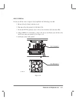
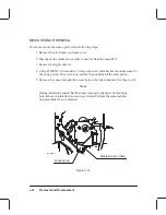
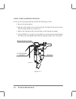
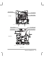
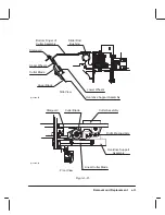
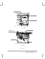
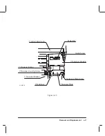
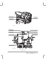
6. Disconnect the encoder cable connector from the paper motor. See Figure 6-19.
Note
Note the orientation of the mark (9 0’clock position) on one side of the drive
roller gear for installation purposes.
7. Using a TORX T-10 screwdriver, remove the two screws that secure the drive roller
gear to the drive roller shaft and remove the gear.
8. Using a TORX T-20 screwdriver, remove the two screws that secure the ink drop
well and remove the well.
9. Using a TORX T-15 screwdriver, remove the two screws that secure the paper motor
to its bracket.
10. Pull the paper motor toward the rear of the plotter until the motor can be removed
from the plotter.
If installing a new motor, apply grease (supplied with the motor) to the motor worm gear.
Note
Ensure that the mark on the drive roller gear faces to the front of the plotter
(9 0’clock position) when the motor worm gear is fully engaged with the
drive roller gear.
Summary of Contents for C2858A
Page 125: ...7 10 Adjustments Calibrations Notes ...
Page 155: ...9 4 Product History Notes ...
Page 164: ...10 9 Parts and Diagrams Illustrated Parts Breakdown C2859A Electronics Enclosure C C2858 3 1 ...
Page 166: ...10 11 Parts and Diagrams Illustrated Parts Breakdown C2858A Electronics Enclosure C C2858 4 1 ...
Page 182: ...10 27 Parts and Diagrams Illustrated Parts Breakdown Paper Drive Assemblies C C2858 12 1 ...
Page 198: ... ...


