8-2
Troubleshooting
DIAGNOSTICS
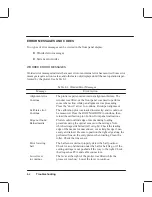
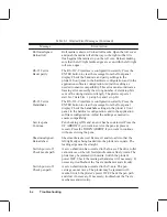
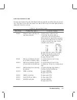
Several types of built-in diagnostic and service tests reside in the DesignJet 650C plotters.
These troubleshooting aids include power-on self tests and mechanical initialization rou-
tines. In addition, worded error messages; system error codes; and internal service menu tests
are provided.
POWER-ON SELF TESTS
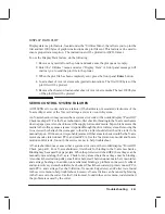
HP C2858A/9A DesignJet 650C plotters will automatically perform a series of internal self
tests, as well as certain initialization sequences, whenever the plotter is switched ON. These
self test and initialization sequences are described in the following paragraphs. As the plotter
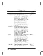
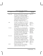
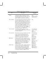
moves through the tests, a series of dots will quickly appear on the display. During a failure
condition, a failure analysis may be performed by either noting the number of dots present on
the display or interpreting the worded message or system error code message displayed.
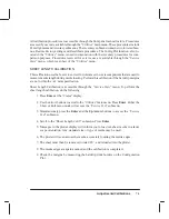
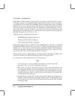
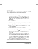
POWER-ON SELF TEST
Self-tests normally run when the plotter is switched on are:
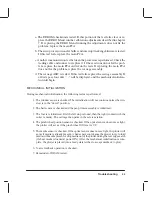
1. Servo processor initialization. The display will read “Servo processor initialized”
when initialization is complete. If the servo processor cannot initialize, replace the
main PCA.
2. The main processor initializes. One dot “.” will be displayed when complete. If this
portion of the test fails, replace the main PCA.
3. The main processor to servo processor communication path is tested. If this portion
of the test fails, replace the main PCA.
4. The ROM checksum is tested. Successful completion of this test will cause two dots
“..” to be displayed. If this portion of the test fails, first replace the EPROMs. If re-
placing the EPROMs does not correct the error, replace the main PCA.
5. The main processor initializes certain firmware modules and communicates with the
carriage processor. If these tests pass, three dots “...” will be displayed and the “Pa-
per” LED will be turned ON.
Summary of Contents for C2858A
Page 125: ...7 10 Adjustments Calibrations Notes ...
Page 155: ...9 4 Product History Notes ...
Page 164: ...10 9 Parts and Diagrams Illustrated Parts Breakdown C2859A Electronics Enclosure C C2858 3 1 ...
Page 166: ...10 11 Parts and Diagrams Illustrated Parts Breakdown C2858A Electronics Enclosure C C2858 4 1 ...
Page 182: ...10 27 Parts and Diagrams Illustrated Parts Breakdown Paper Drive Assemblies C C2858 12 1 ...
Page 198: ... ...

