6-58
Removal and Replacement
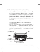
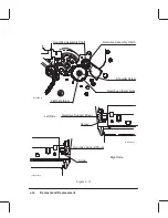
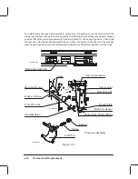
To install, place the pinch arm assembly spring into its bushing. Insert the front end of the
spring into the hole in the pinch arm assembly with the pinch arm 90 degrees from its normal
position. Press the pinch arm assembly back and rotate it to the vertical position. Then slide
the cam bar to the right until the pinch arm assembly is captured in the chassis. The cam bar
must be positioned between the left and right sideplates or the lift mechanism will not work.
Pinchwheel Assembly
Manual Lift Lever
Cam
Washer & Screw
Front Wire Link
Shoulder Screw
Rear Wire Link
Rocker Plate
Cam Journal
Pinch Arm Sensor
Cam Journal Screw
Rocker Plate Tension Spring
Pinch Arm
Spring
Bushing
Pinch Arm Assembly
(C)C2858-29b
(C)C2858-75
(C)C2858-30c
Summary of Contents for C2858A
Page 125: ...7 10 Adjustments Calibrations Notes ...
Page 155: ...9 4 Product History Notes ...
Page 164: ...10 9 Parts and Diagrams Illustrated Parts Breakdown C2859A Electronics Enclosure C C2858 3 1 ...
Page 166: ...10 11 Parts and Diagrams Illustrated Parts Breakdown C2858A Electronics Enclosure C C2858 4 1 ...
Page 182: ...10 27 Parts and Diagrams Illustrated Parts Breakdown Paper Drive Assemblies C C2858 12 1 ...
Page 198: ... ...

