3-20
Installation and Configuration
FRONT PANEL MENUS
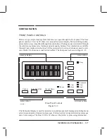
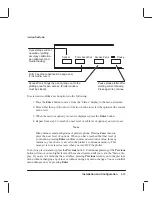
There are seven main menus, each with an option or series of submenus. Pressing the Enter
button from the “Status” display will access the menu structure. Both a short menu and a full
menu are available in the plotter display. The short menu is the default menu and displays the
more commonly used menus. Changing to the short or full menu (Menu mode submenu) is
accessed through the “Utilities” main menu.
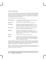
A brief description of the main menus is given below.
Plot Management
Controls plot file management in the queue including queueing,
nesting and number of copy specifications.
Page Format
Specifies the size, orientation and margins for the plots.
Pen Settings
Defines the pen attributes including the palette which contains
individual pen width and shading/color settings. Two custom
palettes of 16 pens each can be defined and stored by the user.
Plotter Setup
Defines basic operating setup including graphics language, dry
time, pen checking and media bypass conditions.
I/O Setup
Controls plotter I/O configuration and interaction with the
controller. For configuring the RS-232 and MIO interfaces and
parameters. Two user customized RS-232 configurations can be
stored in memory.
Demo Plot
Accesses the internal demonstration plot routine.
Utilities
Accesses accuracy calibration procedures. Also contains front
panel menu configuration information, plotter statistic information
(plot size, memory size, firmware revision level, ROM SIMMs
present) and default menu options.
Complete information on using the various menu and submenu options is contained in the HP
C2858A and C2859A DesignJet 650C Using Your Plotter’s Front Panel Guide. Additional
setup information is available in the DesignJet 650C Setting Up For Plotting Guide. Refer to
Chapter 1 in this manual for more information regarding these guides.
Figure 3-12, located at the end of this chapter, provides a diagram of the menu tree showing
the various menus and submenus of the DesignJet 650C plotters. Both the short and full menu
structures are presented on the diagram.
Summary of Contents for C2858A
Page 125: ...7 10 Adjustments Calibrations Notes ...
Page 155: ...9 4 Product History Notes ...
Page 164: ...10 9 Parts and Diagrams Illustrated Parts Breakdown C2859A Electronics Enclosure C C2858 3 1 ...
Page 166: ...10 11 Parts and Diagrams Illustrated Parts Breakdown C2858A Electronics Enclosure C C2858 4 1 ...
Page 182: ...10 27 Parts and Diagrams Illustrated Parts Breakdown Paper Drive Assemblies C C2858 12 1 ...
Page 198: ... ...

