6-7
Removal and Replacement
ELECTRONICS ENCLOSURE COVER REMOVAL
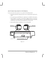
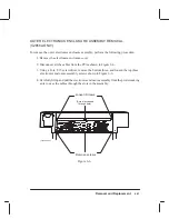
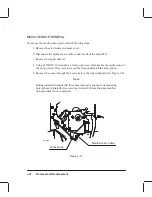
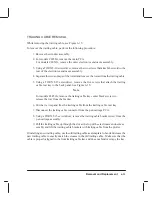
To remove the electronics enclosure cover, perform the following procedure:
1. Switch the plotter OFF and disconnect the ac power cord and interface cable from the
plotter.
2. If a modular input/output (MIO) card is installed, remove the MIO from the plotter.
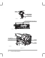
3. Using a TORX T-15 screwdriver, remove the rear sideplate trim pieces and electron-
ics enclosure cover shown in Figure 6-3. The C2858A has 10 cover screws and the
C2859A has 12 cover screws. The trim pieces have two screws each.
4. Gently pull the trim pieces and then the cover off of the plotter.
Figure 6-3.
Rear Trim
Electronics Enclosure Cover
Rear Trim
(C)C2858-32a
Summary of Contents for C2858A
Page 125: ...7 10 Adjustments Calibrations Notes ...
Page 155: ...9 4 Product History Notes ...
Page 164: ...10 9 Parts and Diagrams Illustrated Parts Breakdown C2859A Electronics Enclosure C C2858 3 1 ...
Page 166: ...10 11 Parts and Diagrams Illustrated Parts Breakdown C2858A Electronics Enclosure C C2858 4 1 ...
Page 182: ...10 27 Parts and Diagrams Illustrated Parts Breakdown Paper Drive Assemblies C C2858 12 1 ...
Page 198: ... ...


