6-9
Removal and Replacement
MAIN PCA REMOVAL
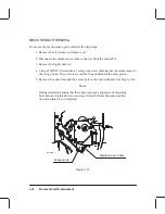
To remove the main PCA, perform the following procedure:
1. Remove the electronic enclosure cover.
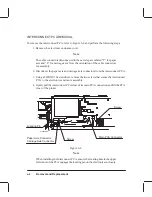
2. Remove the interconnect PCA.
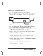
3. Using a 3/16” nut driver, remove the two screws on top of the electronics enclosure
from the RS-232-C connector.
4. Using a TORX T-10 screwdriver, remove the two screws on top of the electronics
enclosure from the parallel connector.
5. Disconnect all the cable connectors from the main PCA.
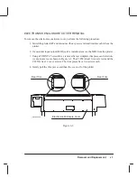
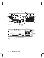
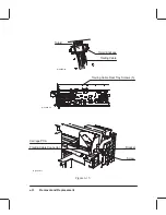
6. Using a TORX T-10 screwdriver, remove the 12 screws securing the main PCA to
the electronics enclosure assembly. See Figure 6-5.
7. Using a 7mm socket or open-end wrench, remove the two nuts that secure the main
PCA to the electronics enclosure assembly.
8. Lift the main PCA clear of the plotter.
If installing a new PCA, do the following:
1. Remove the original EEROM (8-pin IC) from the socket and install it on the replace-
ment PCA.
2. Remove the original EPROMs from their sockets, and install them on the replace-
ment PCA.
3. Remove any SIMMs that were installed on the original PCA.
4. Remove the plastic SIMM guard from the original PCA and install it on the replace-
ment PCA. Install any SIMMs removed from the original PCA.
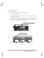
Note
When installing the main PCA, temporarily leave the screws and nuts that
attach the main PCA and the interconnect PCA loose. Tighten the I/O con-
nectors first, then tighten the PCA screws and nuts.
Summary of Contents for C2858A
Page 125: ...7 10 Adjustments Calibrations Notes ...
Page 155: ...9 4 Product History Notes ...
Page 164: ...10 9 Parts and Diagrams Illustrated Parts Breakdown C2859A Electronics Enclosure C C2858 3 1 ...
Page 166: ...10 11 Parts and Diagrams Illustrated Parts Breakdown C2858A Electronics Enclosure C C2858 4 1 ...
Page 182: ...10 27 Parts and Diagrams Illustrated Parts Breakdown Paper Drive Assemblies C C2858 12 1 ...
Page 198: ... ...

