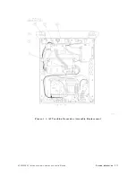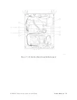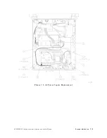
A5
Line
Filter/Switch
Assembly
Replacement
Caution
The
tracking
generator
assemblies
are
static
sensitive
.
P
erform
assembly
procedures
at
static-safe
work
stations
.
Refer
to
Figure
7-1
for
an
example
of
a
static-safe
work
station.
Removal
1.
Remove
the
instrument
cover
as
described
on
page
7-7.
2.
Remove
the
four
screws
1
(two
per
side)
from
the
power
supply
shield.
3.
Remove
the
three
screws
2
connecting
the
power
supply
shield
to
the
chassis
.
Remove
the
shield.
4.
Depress
the
clips
on
the
sides
of
A5W1
P1
connector
3
to
disconnect
A5W1
from
A4W1.
5.
Remove
the
line
module
grounding
nut
4
to
disconnect
A5W3.
6.
T
o
remove
the
front-panel
line
switch,
remove
the
screw
6
securing
the
grounding
wire
to
the
frame
.
7.
Pull
the
line
switch
away
from
the
front
frame
,
and
slip
the
LED
out
of
its
socket.
8.
Remove
the
two
screws
5
that
connect
the
line
module
to
the
chassis
.
9.
Carefully
pull
A5W2
7
out
of
the
harness
clips
8
and
remove
the
A5
assembly
.
Replacement
10.
Replace
the
line
module
into
the
chassis
with
the
plug
prongs
toward
the
top
of
the
tracking
generator
and
the
voltage
selection
switch
toward
the
bottom.
Alternately
tighten
the
two
screws
5
.
11.
Reconnect
A5W3
grounding
wire
with
the
nut
4
and
tighten
it
to
six
inch-pounds
.
12.
Lay
A5W2
7
along
its
path
near
the
harness
clips
8
,
and
slip
the
LED
into
its
slot
on
the
line
switch.
13.
Orient
the
line
switch
so
that
\LINE"
reads
correctly
from
the
outside
.
Tighten
the
grounding
screw
6
to
six
inch-pounds
.
14.
Press
A5W2
into
the
harness
clips
8
.
Reconnect
A5W1
to
A4W1
3
.
15.
Replace
the
power
supply
cover
,
loosely
tighten
the
four
side
screws
1
and
the
three
chassis
screws
2
.
Alternately
tighten
all
screws
to
six
inch-pounds
.
16.
Check
that
the
fuse
in
A5FL1
and
the
voltage
selector
are
correct
for
your
power
mains
.
Refer
to
Chapter
2,
\Installation,"
for
additional
power
requirement
information.
7-16
Service
Information
HP
85640A
RF
T
racking
Generator
Operation
and
Service
Manual
Summary of Contents for 85640A
Page 2: ...HP 85640A RF Tracking Generator Operation and Service Manual ABCDE Printed in USA ...
Page 111: ......
Page 169: ......


