


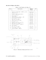
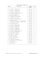
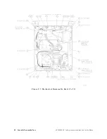


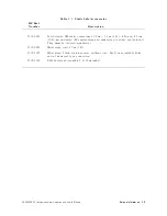

3.
P
ower
Level
A
djustments
Assembly
A
djusted
A3
interface
assembly
Related
P
erformance
T
est
Level
atness
Description
The
OUTPUT
LEVEL
vernier
is
set
to
04
dBm
and
the
voltage
at
the
vernier
control's
wiper
is
checked
for
+2.5
V
(the
electrical
center
of
the
control).
If
necessary
,
the
vernier
control
knob
is
reset.
The
gain
and
oset
of
the
power
level
control
circuitry
is
adjusted
to
yield
010
dBm
at
the
0
dBm
vernier
setting
and
020
dBm
at
the
010
dBm
vernier
setting
(the
OUTPUT
LEVEL
attenuator
is
set
to
010
dB).
The
sweep-plus-tune
gain
(S+T
GAIN)
is
adjusted
for
the
same
amplitude
at
2.9
GHz
as
at
300
MHz.
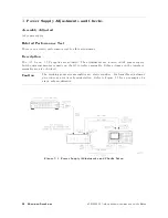
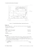
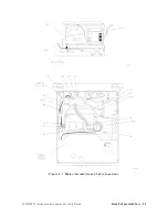
Caution
The
tracking
generator
assemblies
are
static
sensitive
.
P
erform
this
adjustment
procedure
at
a
static-safe
workstation.
Refer
to
Figure
7-1
for
an
example
of
a
static-safe
workstation.
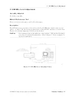
Figure
5-5.
P
ower
Level
A
djustment
Setup
5-12
Adjustment
Procedures
HP
85640A
RF
T
racking
Generator
Operation
and
Service
Manual
Summary of Contents for 85640A
Page 2: ...HP 85640A RF Tracking Generator Operation and Service Manual ABCDE Printed in USA ...
Page 111: ......
Page 169: ......


