


Troubleshooting
the
HP
85640A
RF
Tracking
Generator
Circuits
The
A2
tracking
generator
,
A1
attenuator
assemblies
,
and
A4
power
supply
may
be
replaced
if
they
are
defective;
these
assemblies
are
not
eld
serviceable
.
The
A2
tracking
generator
assembly
is
available
as
a
rebuilt
exchange
assembly
.
Refer
to
the
rebuilt
exchange
assembly
procedure
in
this
chapter
for
more
information
about
obtaining
rebuilt,
factory-tested
assemblies
.
A1
Attenuator
The
A1
Attenuator
is
a
70
dB
step
attenuator
,
with
three
sections
that
provide
attenuation
values
of
10,
20
and
40
dB
.
The
attenuator
includes
a
dc
blocking
capacitor
on
its
output
to
prevent
damage
from
reverse
input
voltages
less
than
630
V
dc
.
A2
Tracking
Generator
The
A2
tracking
generator
consists
of
several
smaller
circuits
.
The
A2
is
not
component-level
repairable;
a
rebuilt
exchange
assembly
is
available
.
P
art
numbers
are
in
T
able
6-1
and
the
rebuilt
exchange
assembly
procedure
is
at
the
beginning
of
this
chapter
.
The
tracking
generator
is
unique
because
it
recreates
only
onehost-analyzer
intermediate
frequency
,
thereby
minimizing
isolation
problems
associated
with
the
tracking
generator
.
The
function
blocks
of
the
A2
tracking
generator
circuitry
are
described
below
.
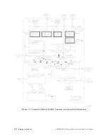
Refer
to
Figure
7-9
for
the
location
of
these
circuits
in
the
block
diagram.
Tracking
oscillator
The
tracking
oscillator
enables
the
ne
adjustment
of
the
tracking
generator
output
frequency
to
compensate
for
the
frequency
inaccuracies
of
the
host
spectrum
analyzer's
10.7
MHz
IF
.
The
tracking
oscillator
determines
the
residual
FM
and
frequency
drift
of
the
tracking
generator
.
The
182.14
MHz
output
frequency
is
obtained
by
doubling
the
output
of
a
crystal
oscillator
operating
at
91.07
MHz.
Upconverter
The
upconverter
mixes
the
tracking
oscillator
output
with
the
600
MHz
signal
coming
from
the
A3
Interface
Assembly
.
The
upconverter
also
contains
a
lter
which
passes
only
the
782.14
MHz
upper
sideband.
P
entupler
The
pentupler
multiplies
the
782.14
MHz
signal
by
ve
to
generate
3.9107
GHz,
which
equals
the
host
spectrum
analyzer's
1st
IF
.
A
dual-cavity
band-pass
lter
centered
at
3.9107
GHz
eliminates
all
unwanted
harmonics
of
782.14
MHz.
Modulator
The
output
of
the
pentupler
passes
through
a
modulator
which
adjusts
the
power
level
going
into
the
output
mixer
.
The
modulator
is
controlled
by
an
ALC
circuit
on
the
bias
board
controlled
by
a
detector
in
the
output
amplier
.
If
the
detected
output
power
is
too
high,
the
ALC
drives
the
modulator
to
decrease
the
input
level
into
the
output
mixer
,
which
decreases
the
output
power
.
Coupler
The
1st
LO
INPUT
signal
from
the
host
spectrum
analyzer
is
coupled
and
buered
to
drive
the
output
mixer
.
The
main
line
of
the
coupler
is
terminated
in
50
by
A
T1.
The
loss
through
the
coupler
main
line
is
less
than
2.5
dB
.
Output
mixer
The
3.9107
GHz
signal
from
the
modulator
goes
into
the
RF
port
of
the
output
mixer
.
The
LO
port
of
the
output
mixer
is
driven
by
the
HP
85640A
RF
T
racking
Generator
Operation
and
Service
Manual
Service
Information
7-21
Summary of Contents for 85640A
Page 2: ...HP 85640A RF Tracking Generator Operation and Service Manual ABCDE Printed in USA ...
Page 111: ......
Page 169: ......


