


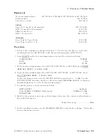


8.
Frequency
Tracking
Range
Equipment
Host
spectrum
analyzer
.
.
.
.
.
.
HP
8560A/E,
8561A/B/E,
HP
8562A/B
,
or
HP
8563A/E
P
ower
splitter
.
.
.
.
.
.
.
.
.
.
.
.
.
.
.
.
.
.
.
.
.
.
.
.
.
.
.
.
.
.
.
.
.
.
.
.
.
.
.
.
.
.
.
.
.
.
.
.
.
.
.
.
.
.
.
HP
11667A
Frequency
counter
.
.
.
.
.
.
.
.
.
.
.
.
.
.
.
.
.
.
.
.
.
.
.
.
.
.
.
.
.
.
.
.
.
.
.
.
.
.
.
.
.
.
.
.
.
.
.
.
.
.
.
.
HP
5343A
Cables
Type
N,
62
cm
(24
in)
(2
required)
.
.
.
.
.
.
.
.
.
.
.
.
.
.
.
.
.
.
.
.
.
.
.
.
.
.
.
.
.
.
.
.
.
.
HP
11500B/C
BNC,
62
cm
(24
in)
(3
required)
.
.
.
.
.
.
.
.
.
.
.
.
.
.
.
.
.
.
.
.
.
.
.
.
.
.
.
.
.
.
.
.
.
.
.
.
.
.
.
.
8120-1839
SMA,
52
cm
(20
in)
.
.
.
.
.
.
.
.
.
.
.
.
.
.
.
.
.
.
.
.
.
.
.
.
.
.
.
.
.
.
.
.
.
.
.
.
.
.
.
.
.
.
.
.
.
.
.
.
.
.
.
.
5061-9038
BNC,
122
cm
(48
in)
.
.
.
.
.
.
.
.
.
.
.
.
.
.
.
.
.
.
.
.
.
.
.
.
.
.
.
.
.
.
.
.
.
.
.
.
.
.
.
.
.
.
.
.
.
.
.
.
.
.
HP
10503A
A
dapters
Type
N
(m)
to
Type
N
(m)
.
.
.
.
.
.
.
.
.
.
.
.
.
.
.
.
.
.
.
.
.
.
.
.
.
.
.
.
.
.
.
.
.
.
.
.
.
.
.
.
.
.
.
.
.
1250-1475
Type
N
(m)
to
APC
3.5
(f)
.
.
.
.
.
.
.
.
.
.
.
.
.
.
.
.
.
.
.
.
.
.
.
.
.
.
.
.
.
.
.
.
.
.
.
.
.
.
.
.
.
.
.
.
.
1250-1745
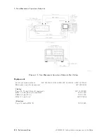
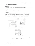
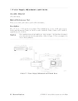
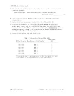
Procedure
1.
Connect
the
equipment
as
shown
in
Figure
4-9.
Use
the
type
N
cable
to
connect
the
tracking
generator's
RF
OUTPUT
to
the
host
spectrum
analyzer's
INPUT
50.
2.
Press
4
PRESET
5
on
the
host
spectrum
analyzer
and
set
the
controls
as
follows:
CENTER
FREQ
.
.
.
.
.
.
.
.
.
.
.
.
.
.
.
.
.
.
.
.
.
.
.
.
.
.
.
.
.
.
.
.
.
.
.
.
.
.
.
.
.
.
.
.
.
.
.
.
.
.
.
.
.
500
MHz
SP
AN
.
.
.
.
.
.
.
.
.
.
.
.
.
.
.
.
.
.
.
.
.
.
.
.
.
.
.
.
.
.
.
.
.
.
.
.
.
.
.
.
.
.
.
.
.
.
.
.
.
.
.
.
.
.
.
.
.
.
.
.
.
.
.
.
.
.
.
0
Hz
RES
BW
.
.
.
.
.
.
.
.
.
.
.
.
.
.
.
.
.
.
.
.
.
.
.
.
.
.
.
.
.
.
.
.
.
.
.
.
.
.
.
.
.
.
.
.
.
.
.
.
.
.
.
.
.
.
.
.
.
.
.
.
.
300
Hz
3.
If
the
host
spectrum
analyzer
is
an
HP
8561A,
HP
8562A,
or
HP
8562B
,
press
4
SWEEP
5
NNNNNNNNNNNNNNNNNNNNNNNNNNNNNNNNNNNNNNNNNNNNNNN
REAR
PNL
OUTPUT
NNNNNNNNNNNNNNNNNNNNNNNNNNNNNNNNNNNNNNNNNNNN
.5
V/GHz
(FAV)
.
4.
If
the
host
spectrum
analyzer
is
an
HP
8560A/E,
HP
8561B/E,
or
HP
8563A/E,
press
4
AUX
CTRL
5
NNNNNNNNNNNNNNNNNNNNNNNNNNNNNNNN
REAR
PANEL
NNNNNNNNNNNNNNNNNNNNNNNNNNNNNNNNNNNNNNNNNNNN
.5
V/GHz
(FAV)
.
On
the
tracking
generator
,
set
the
OUTPUT
LEVEL
vernier
knob
to
05
dBm.
Set
the
OUTPUT
LEVEL
attenuator
knob
to
0
dB
,
then
adjust
TRA
CKING
ADJUST
to
display
a
maximum
signal
level
on
the
host
spectrum
analyzer
.
5.
Set
the
frequency
counter
controls
as
follow:
SAMPLE
RA
TE
.
.
.
.
.
.
.
.
.
.
.
.
.
.
.
.
.
.
.
.
.
.
.
.
.
.
.
.
.
.
.
.
.
.
.
.
.
.
.
.
.
.
.
.
.
.
.
.
.
.
.
.
midrange
10Hz-500MHz
/
500MHz-26.5GHz
Switch
.
.
.
.
.
.
.
.
.
.
.
.
.
.
.
.
.
.
.
.
.
.
500MHz-26.5GHz
RESOLUTION
.
.
.
.
.
.
.
.
.
.
.
.
.
.
.
.
.
.
.
.
.
.
.
.
.
.
.
.
.
.
.
.
.
.
.
.
.
.
.
.
.
.
.
.
.
.
.
.
.
.
.
.
.
.
.
.
.
.
.
1
Hz
6.
W
ait
for
the
counter
to
gate
two
or
three
times
and
record
the
counter
reading
below
as
the
peaked
frequency
.
P
eaked
frequency
MHz
7.
On
the
tracking
generator
,
set
the
TRA
CKING
ADJUST
control
fully
clockwise
.
Notice
that
this
is
a
multi-turn
control.
HP
85640A
RF
T
racking
Generator
Operation
and
Service
Manual
P
erformance
T
ests
4-33
Summary of Contents for 85640A
Page 2: ...HP 85640A RF Tracking Generator Operation and Service Manual ABCDE Printed in USA ...
Page 111: ......
Page 169: ......


