


4.
Tracking
Oscillator
Range
A
djustments
4.
Tracking
Oscillator
Range
A
djustments
Assemblies
A
djusted
A2
tracking
generator
assembly
A3
interface
assembly
Related
P
erformance
T
est
Tracking
adjustment
range
Description
The
centering
of
the
tracking
oscillator
range
is
adjusted
in
the
factory
to
ensure
that
the
tracking
adjustment
works
properly
.
Over
a
period
of
5
years
,
however
,
the
center
frequency
of
the
tracking
oscillator
range
may
drift
outside
of
acceptable
limits
.
These
limits
are
tested
with
the
tracking
adjustment
range
performance
test
in
Chapter
4
of
this
manual.
P
erform
this
adjustment
only
if
the
tracking
adjustment
range
performance
test
has
failed.
This
adjustment
centers
the
tracking
oscillator
range
.
Typically
,
performing
the
ne
adjustment
on
the
A3
interface
assembly
is
sucient.
In
some
cases
,
however
,
adjusting
the
A2
tracking
generator
coarse
adjustment
is
necessary
.
The
coarse
adjustment,
A2C3,
is
rated
for
a
maximum
of
10
adjustment
cycles
.
Because
of
this
limitation,
adjust
A2C3
only
when
absolutely
necessary
.
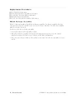
Caution
The
tracking
generator
assemblies
are
static-sensitive
.
P
erform
this
adjustment
procedure
at
a
static-safe
workstation.
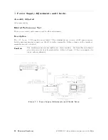
Refer
to
Figure
7-1
for
an
example
of
a
static-safe
workstation.
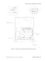
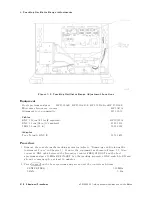
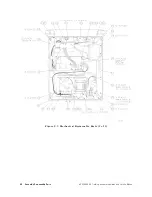
Figure
5-7.
Tracking
Oscillator
Range
A
djustment
HP
85640A
RF
T
racking
Generator
Operation
and
Service
Manual
Adjustment
Procedures
5-15
Summary of Contents for 85640A
Page 2: ...HP 85640A RF Tracking Generator Operation and Service Manual ABCDE Printed in USA ...
Page 111: ......
Page 169: ......


