

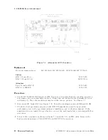


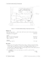
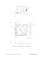


4.
Tracking
Oscillator
Range
A
djustments
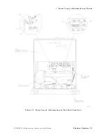
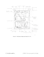
Figure
5-8.
Tracking
Oscillator
Range
A
djustment
Locations
Equipment
Host
spectrum
analyzer
.
.
.
HP
8560A/E,
HP
8561A/B/E,
HP
8562A/B
or
HP
8563A/E
Microwave
frequency
counter
.
.
.
.
.
.
.
.
.
.
.
.
.
.
.
.
.
.
.
.
.
.
.
.
.
.
.
.
.
.
.
.
.
.
.
.
.
.
.
.
.
HP
5343A
Alignment
tool,
nonmetallic
.
.
.
.
.
.
.
.
.
.
.
.
.
.
.
.
.
.
.
.
.
.
.
.
.
.
.
.
.
.
.
.
.
.
.
.
.
.
.
.
.
.
.
8710-0033
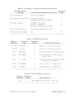
Cables
BNC,
122
cm
(48
in)
(2
required)
.
.
.
.
.
.
.
.
.
.
.
.
.
.
.
.
.
.
.
.
.
.
.
.
.
.
.
.
.
.
.
.
.
.
.
.
.
.
HP
10503A
BNC,
62
cm
(24
in)
(3
required)
.
.
.
.
.
.
.
.
.
.
.
.
.
.
.
.
.
.
.
.
.
.
.
.
.
.
.
.
.
.
.
.
.
.
.
.
.
.
.
.
8120-1839
SMA,
52
cm
(20
in)
.
.
.
.
.
.
.
.
.
.
.
.
.
.
.
.
.
.
.
.
.
.
.
.
.
.
.
.
.
.
.
.
.
.
.
.
.
.
.
.
.
.
.
.
.
.
.
.
.
.
.
.
5061-9038
A
dapter
Type
N
(m)
to
BNC
(f)
.
.
.
.
.
.
.
.
.
.
.
.
.
.
.
.
.
.
.
.
.
.
.
.
.
.
.
.
.
.
.
.
.
.
.
.
.
.
.
.
.
.
.
.
.
.
.
.
.
1250-1476
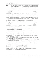
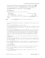
Procedure
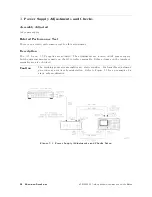
1.
Remove
the
cover
from
the
tracking
generator
(refer
to
\Removing
and
Replacing
the
Instrument
Cover"
in
Chapter
7).
Connect
the
equipment
as
shown
in
Figure
5-7.
Also
connect
a
BNC
cable
between
the
frequency
counter
FREQ
STD
OUT
and
the
host
spectrum
analyzer
10
MHz
REF
IN/OUT
.
Set
the
tracking
generator
LINE
switch
to
ON
and
allow
it
to
warm
up
for
at
least
10
minutes
.
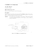
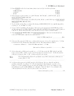
2.
Press
4
PRESET
5
on
the
host
spectrum
analyzer
and
set
the
controls
as
follows:
CENTER
FREQ
.
.
.
.
.
.
.
.
.
.
.
.
.
.
.
.
.
.
.
.
.
.
.
.
.
.
.
.
.
.
.
.
.
.
.
.
.
.
.
.
.
.
.
.
.
.
.
.
.
.
.
.
.
300
MHz
SP
AN
.
.
.
.
.
.
.
.
.
.
.
.
.
.
.
.
.
.
.
.
.
.
.
.
.
.
.
.
.
.
.
.
.
.
.
.
.
.
.
.
.
.
.
.
.
.
.
.
.
.
.
.
.
.
.
.
.
.
.
.
.
.
.
.
.
.
.
0
Hz
5-16
Adjustment
Procedures
HP
85640A
RF
T
racking
Generator
Operation
and
Service
Manual
Summary of Contents for 85640A
Page 2: ...HP 85640A RF Tracking Generator Operation and Service Manual ABCDE Printed in USA ...
Page 111: ......
Page 169: ......


