2.
600
MHz
Level
A
djustment
13.
Calculate
the
desired
attenuation
value
by
adding
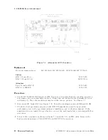
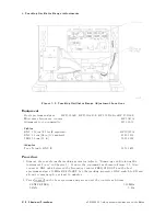
the
current
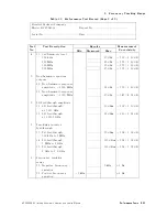
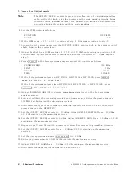
attenuation
value
to
the
attenuation
dierence
.
desired
attenuation
=
current
attenuation
value
+
attenuation
dierence
Desired
attenuation:
dB
14.
Select
a
new
value
for
pad
A3U4
using
T
able
5-5 ,
based
on
the
desired
attenuation
calculated
above
.
15.
Replace
the
A3
interface
assembly
top
shield.
Set
the
LINE
switch
to
ON.
16.
On
the
host
spectrum
analyzer
,
press
4
PEAK
SEARCH
5
NNNNNNNNNNNNNNNNNNNNNNNNNNNNNNNNNNNNNN
MARKER
DELTA
4
FREQUENCY
5
NNNNNNNNNNNNNNNNNNNNNNNNNNNNNNNNNNN
CENTER
FREQ
.
Use
the
step
keys
to
set
the
spectrum
analyzer
to
each
of
the
center
frequencies
listed
in
T
able
5-6 .
At
each
frequency
setting,
press
4
PEAK
SEARCH
5
and
record
the
marker
amplitude
in
T
able
5-6
for
the
appropriate
frequency
.
The
marker
amplitude
should
be
less
than
the
specication
listed.
17.
Replace
the
BNC
cable
at
A3J5
with
the
W5
cable
.
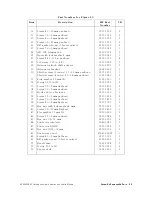
T
able
5-5.
Attenuation
V
alues
of
P
ad
A3U4
HP
P
art
Number
Manufacturer's
P
art
Number*
Attenuation
(dB)
0955-0308
MA
T-1
1
0955-0309
MA
T-2
2
0955-0310
MA
T-3
3
0955-0311
MA
T-4
4
0955-0312
MA
T-5
5
0955-0313
MA
T-6
6
0955-0314
MA
T-7
7
*These
manufacturer's
part
numbers
are
for
Mini
Circuits
Lab
,
Inc
.
parts
.
P
art
numbers
for
other
manufacturers'
parts
may
be
dierent.
5-10
Adjustment
Procedures
HP
85640A
RF
T
racking
Generator
Operation
and
Service
Manual
Summary of Contents for 85640A
Page 2: ...HP 85640A RF Tracking Generator Operation and Service Manual ABCDE Printed in USA ...
Page 111: ......
Page 169: ......


