FINAL
TRIM
SIZE
:
7.0
in
x
8.5
in
B
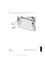
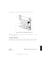
Figure
B-2.
Connector
Holes
(Example)
in
the
VME
RFI
Co
v
er
8.
Determine
the
extension
cable
connector
dimensions
and
lo
cation,
and
then
cut
out
the
connector
holes,
as
in
the
ab o
v
e
example.
( Note
that
your
c
ongur
ation
may
b
e
dier
ent
fr
om
the
example
il
lustr
ation
).
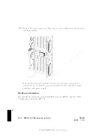
9.
Install
the
extension
cable
connector
in
the
VME
mo
dule
RFI
co
v
er,
and
then
plug
the
other
end
in
to
the
VMEbus
accessory
card
connector.
B-10
VME
and
EISA
Accessory
Cards
DRAFT
2/5/97
11:31


