65-0315—02
6
The number of Sola controls connected and powered up to
the S7999D are displayed on the Home page.
Images can be customized on the S7999D display. Each
image can be placed on a USB memory stick along with a
special command file (
args.txt
) directing the image files to be
copied to the S7999D at boot-time. In
args.txt
on the USB
memory stick, you place a “
/f
” command which stands for
“files” and then you list the files you want copied from the USB
card after it with each file name separated by at least one
space, e.g.:
/f HomePageBkgd.png
Images to be changed:
1.
Home page background - must be named
"
HomePageBkgd.png
", "
HomePageBkgd.bmp
", or
"
HomePageBkgd.jpg
", have PNG, BMP or JPG file for-
mat, and be less than or equal to 800 x 480 pixels.
2.
Home page logo - must be named "
oemlogo.png
",
"
oemlogo.bmp
", "
oemlogo.jpg
", have PNG, BMP or
JPG file format and be less than or equal to 380 x 68
pixels.
3.
Screen saver - must be called
"
screensaver.png
","
screensaver.bmp
",
"
screensaver.jpg
", have PNG, BMP or JPG file for-
mat, and be less than or equal to 800 x 480 pixels.
On System applications, each SOLA Control is represented
on the Home page by an icon and name. Pressing the icon
allows the user to zoom in on that boiler and see its specific
details.
These details are provided on a new page, which can include
additional buttons that display detail and operation
information, which itself leads to other pages. The pages are
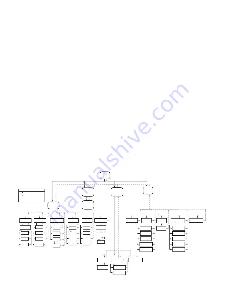
traversed in a tree structure method, as shown in Fig. 8.
The SOLA icons will appear in one of four colors indicating the
boiler status.
•
Blue
: Normal operation
•
Red
: Lockout condition
•
Yellow
: Holding mode
•
Gray
: Communication error (disconnected or power off)
Up to 8 systems can be displayed on the Home page. The
name of each boiler is displayed next to the SOLA icon button.
When Lead Lag is enabled, the system header temperature
and firing rate are displayed for each System. When the
burner is in standby or not firing the firing rate is not displayed.
NOTE: The boiler name may be cut off on the Home
page when all icons are present.
The Home page also includes buttons for Lead Lag
configuration when lead lag master and slave in the SOLA
control is enabled.
Pressing the Setup button on the Home page displays
miscellaneous setup and diagnostic functions. It also contains
the setup configuration for BAS applications.
The “Control snapshot” button allows the user to dump the
current status and/or configuration settings of any SOLA
controller into a text document. The text document can be
viewed on the display, saved to flash for later viewing, and can
be written to a USB stick for viewing on a PC or file transfer.
Pressing the SOLA icon opens that control’s status page. Go
to “Configure” button to continue.
Fig. 8. S7999D display page flow.
HOME
PAGE
CONTROL
ICON
M32739
SETUP
+ VIEW
LEAD
LAG
LEAD
LAG
MASTER
– VIEW
LEAD
LAG
SYNCHRONIZE
DISPLAY
SETUP
CONTROL
SETUP
DISPLAY
DIAGNOSTICS
CONFIGURE
Configuration
Groups
Login
Logout
Verify
OPERATION
CH
Login
DHW
Annunciation
DIAGNOSTICS
Diagn.
Test
Burner
Control
Digital
I/O
Analog
I/O
DETAILS
History
Alerts
Diagn.
Analysis
HISTORY
OK
Lockouts
Alerts
Silence
MODULATION
?
SETPOINTS
PUMPS
KEY
BUTTON
FLOW
BACK ICON FLOW
HOME ICON ALWAYS TAKES
YOU TO THE HOME PAGE
CHANGE
ADDRESS
SET
DATE/TIME
RENAME
CONTROL
REMOVE
CONTROL
PM
CONFIGURATION
MODBUS
CONFIGURATION
CALIBRATION
SCREEN
AUDIO
TEST
VIDEO
TEST
SCREEN
SNAP-SHOT
DISPLAY
RESET
CONTROL
SNAPSHOT
CONFIGURE
DETAILS
ADVANCED
SETTINGS
HISTORY
ANALYSIS
DIAGNOSTICS


