


User’s Manual ver. 2.0
CD3200 up to110A
Honeywell
15
www.honeywell.com/imc
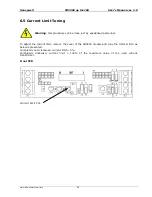
5.3
Wiring connection
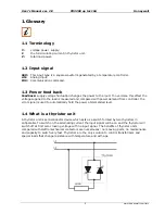
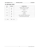
5.3.1 CD3200 15-25A
POW
E
R UN
IT
Input
CT
Reset
- +
RS485-
B
1
6
5
7
8
9
10
11
12
13
14
15
16
17
18
2
A2+
3
A1-
4
RS485-
A
COM
NO/NC
H.B.
Contact
8V
E
x
te
rnal
Ca
lib
rat
io
n
+ -
L1
L2
CT
**
* The user installation must be protect by
electromagnetic circuit breaker or by fuse
isolator
** If the Auxiliary Voltage (written on the
identification label) is different from Supply
Voltage (to the load ), use an external
transformer as designated above.
NOTE:
IMPORTANT
To work, terminals 3-4 must be linked.
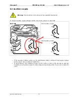
The auxiliary voltage supply of CD3200 unit must be connected as above, and must be
syncronized with load voltage power supply (L1, L2).
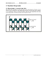
5.3.2 CD3200 35-45A
POW
E
R
U
N
IT
Input
CT
Reset
- +
RS485-
A
1
6
2
7
3
8
4
9
5
10
RS485-
B
COM
NO/NC
H.B.
Contact
8V
E
x
te
rna
l
C
a
lib
ra
tio
n
+ -
1
6
5
7
8
9
10
11
12
13
14
15
16
17
18
2
A2+
3
A1-
4
CT
L1
L2
**
* The user installation must be protect by
electromagnetic circuit breaker or by fuse
isolator
** If the Auxiliary Voltage (written on the
identification label) is different from Supply
Voltage (to the load ), use an external
transformer as designated above.
NOTE:
IMPORTANT
To work, terminals 3-4 must be linked.
The auxiliary voltage supply of CD3200 unit must be connected as above, and must be
syncronized with load voltage power supply (L1, L2).