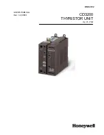


Honeywell
CD3200 up to110A
User’s Manual ver. 2.0
www.honeywell.com/imc 8
3. Ordering information
Model CD3200
1 2 3 4 5 6 7 8
CD3200
Ex:CD3200
90A/ 400/ 480/ 460/ SSR/ ZC/ V2/
UL
1 Nominal current of CD3200M
15A
45A
110A
25A
60A
35A
90A
2 Operating Load Voltage (incoming voltage supply)
Specify the value of the line supply.
3 Max VOLTAGE of CD3200
480V
600V
The voltage on the identification label must be equal or more than
operating voltage. The minimum voltage supply to the load is 24V.
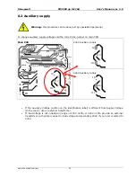
4 Auxiliary Voltage
230V
200÷230V ±15%; 10VA
460V
300÷460V ±15%; 10VA
600V
600V ±15%; 10VA (on request)
5 Input
SSR
4÷30VDC
0-10V
0÷10V analog input
4-20mA 4÷20mA analog input
10K pot Potentiometer
6 Firing
PA
Phase Angle + Current Limit
S + PA Soft Start + Phase Angle + Current Limit
7 Feedback
V
Voltage feedback (V)
V2
Square Voltage feedback (V²)
VxI
Power feedback (VxI) (option)
8 Options
COMM
MODBUS protocol in RS485 is standard
CD-KP
External Keypad
HB
Heater Break Alarm
FAN110 Fan voltage supply 110VAC
±
15% (std 230VAC
±
15%) 14W
50/60Hz
UL
UL Certification
EF
External fuse and fuseholder
NF
No Fuse