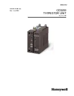


Honeywell
CD3200 up to110A
User’s Manual ver. 2.0
www.honeywell.com/imc 12
5. Wiring Instructions
Warning:
this procedure can be done just by specialized personnel.
CD3000M unit has isolated heatsink. For safety connect the heatsink to hearth using its terminal
with hearth symbol.
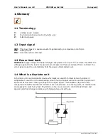
CD3000M can be susceptible to airborne interferences from near equipment or from interferences
on main supply, so a number of precautions must be taken.
•
Contactors coils and chokes must have in parallel a RC filter and must be supplied with a
different voltage line.
•
All input/output signal must use screened bifilar wires.
•
Signal input and output must not routing in same cable try and must not be parallel.
•
Local regulations regarding electrical installation should be rigidly observed.
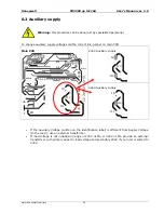
3.3.2 Auxiliary terminals
Before connect or disconnect, make sure that the power, control cables and wires are
insulated from the voltage.
Terminal Description
1
- External Calibration command 24Vdc max
2
+ External Calibration command 24Vdc max
3
Reset
4
Reset
5
+ Output Command signal to CD3200 (Internal Connections)
6
- Output Command signal to CD3200 (Internal Connections)
A2+
+ Input command signal 4÷20mA, 0÷10V
A1-
- Input command signal 4÷20mA, 0÷10V
7 RS485 A
8 RS485 B
9
8Vdc stabilized 1mA MAX potentiometer power supply
10
Common relay H.B. alarm
11
NC/NO H.B. relay alarm
12
External Current Profile
13
CT input with H.B. option
14
CT input with H.B. option
15
Nc not connected
16
Auxiliary supply voltage 240-440Vac
17
Ground
18
Auxiliary supply voltage 240-440Vac
5.1.1 Power Terminals
Before connect or disconnect, make sure that the power, control cables and wires are
insulated from the voltage
Terminal Description
L1 Line
Input
T1 Load
Output