63
7.1 Thru-Shaft Motor Bearing Pre-Load
Introduction
The thru-shaft assembly is a key component in
the Stripe Hog system. It is responsible for turn-
ing the spray bar and holds the blasting head
components together. With proper, routine care
your thru-shaft assemblies will provide you with
many years of reliable service.
We call it the thru-shaft assembly because the
shaft that holds and spins the spray bar runs
through the hydraulic motor. The Thru-Shaft itself
has up to 12 gallons per minute of water running
through it at up to 40,000 psi. The friction of that
much flow at that high of pressure causes a net
thrust of 1,000 lbs.
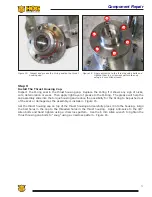
To support the Thru-Shaft against the thrust, we
use an angular contact bearing that we call the
“thrust bearing.” This bearing is found inside the
top section of the assembly as you can see in the
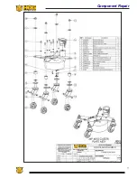
schematics and exploded parts view in later pages.
It is imperative that the thru-shaft be held in a
precise vertical position so it can perform properly.
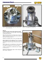
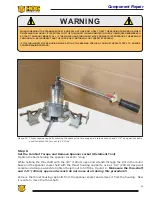
This is accomplished using what we call a spanner
nut. The spanner nut threads onto the thru-shaft
and rests on top of the thrust bearing. By turn-
ing the spanner nut clockwise, we can raise the
thru-shaft position in the assembly. Conversely, by
turning it counterclockwise we can lower it within
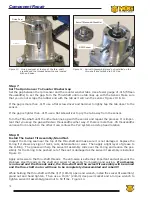
the assembly. Turning the spanner nut is called
“Adjusting the Preload.”
It is important to set the preload on a regular
basis. It only takes about 20 minutes to complete
the process and we recommend it to be done every
40 hours of use. As the thrust bearing wears down
the thru-shaft is lowered. As the shaft lowers, the
motor becomes less powerful and less efficient
because oil can bypass the internal gears.
We have developed a specific process to walk
you through step by step. In the following pages
you will learn all that you need to know to ensure
many years of reliable service. We highly recom-
mend that you follow the procedure carefully and
exactly as described. If you have any questions
please contact the Technical Support Team. We are
available 24 hours every day of the year.
Section 7:
Component Repair
Summary of Contents for Stripe Hog SK3000
Page 1: ...3 K Operations Manual...
Page 2: ...2...
Page 14: ...14 THIS PAGE WAS LEFT BLANK INTENTIONALLY...
Page 62: ...62 THIS PAGE WAS LEFT BLANK INTENTIONALLY...
Page 77: ...77 Component Repair HOG TECHNOLOGIES...
Page 79: ...79 Component Repair HOG TECHNOLOGIES...
Page 81: ...81 Component Repair HOG TECHNOLOGIES...
Page 82: ...82 NOTES...
Page 83: ...83 JETSTREAM UHP PUMP FLUID END Drawings and Schematics Appendix A HOG TECHNOLOGIES...
Page 86: ...86 THIS PAGE WAS LEFT BLANK INTENTIONALLY...
Page 90: ...90 THIS PAGE WAS LEFT BLANK INTENTIONALLY...
Page 92: ...92 THIS PAGE WAS LEFT BLANK INTENTIONALLY...
Page 104: ...104 THIS PAGE WAS LEFT BLANK INTENTIONALLY...
Page 107: ...107...


