26
SK3000 Systems
WARNING
material being removed.
The UHP system is activated by engaging the PTO
clutch and setting engine RPM to the desired oper
-
ating pressure setting (typically 1500 RPM - 2200
RPM max.) There may be some variation of this
depending on the engine and other components
unique to your unit. When setting pressure AL-
WAYS ensure that the system pressure drops to
less than 100 PSI (7 Bar) immediately when the
UHP switch is turned off. If this does not relieve
system pressure immediately to below 100 PSI
when released, do not use the equipment until
repairs are made to the dump valve.
The high pressure pump requires a constant water
supply at a minimum of 30 PSI (2.1 Bar) from the
charge water system to operate properly. Always
make sure there is enough water in the tank before
starting the engine and engaging the PTO clutch
to activate the UHP pump. The pressure gauge
for the charge water system is near the water fil
-
ters and the pressure gauge for the UHP system
is located on the UHP pump. The gauges should
be monitored frequently whenever waterblasting
operations are underway. If the pressure rises
or drops outside of the normal operating range
in either system, stop waterblasting operations
immediately, disengage the PTO and shutdown
the engine. Then find and correct the problem
before resuming blasting operations.
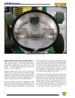
A rupture disc is installed on the high pressure
side of the UHP pump to protect the waterblasting
system against unusually high spikes in pressure.
The disc is designed to burst and immediately
relieve pressure when the system water pressure
exceeds the disc burst pressure. If the rupture
disc bursts it will have to be replaced before
waterblasting operations can resume, therefore,
you should keep spare rupture discs of the proper
pressure rating on hand. You should test the
system at low pressure and correct the problem
that caused the disc to burst before resuming high
pressure operations.
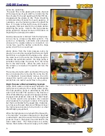
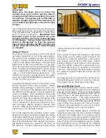
Rupture disc burst pressure ratings are unique to
each unit and critical to operator safety. Refer to
the label on the rupture disc assembly or contact
Hog Technologies Customer Service for the correct
rupture disc rating for your equipment. Never
install a rupture disc with a burst pressure
rating higher than recommended.
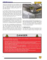
EXcESSIVE PRESSURE IN THE HIGH PRESSURE BLASTING
SYSTEM cAN cAUSE EXTENSIVE DAMAGE TO EqUIPMENT
AND SEVERE INjURY OR EVEN DEATH TO PERSONNEL. IF A
RUPTURE DISc BURSTS IT USUALLY INDIcATES A PROBLEM
THAT NEEDS TO BE cORREcTED BEFORE wATERBLASTING
OPERATIONS cAN RESUME. NEVER INSTALL RUPTURE DIScS
wITH A HIGHER BURST RATING THAN REcOMMENDED.
The filters in the charge pressure line immediately
before the UHP pump remove any debris prior
to the water entering the high pressure system.
These filters prevent damage caused by debris in
the high pressure system and are critical to the
proper operation of the waterblasting system.
They should be checked frequently and replaced
as necessary, typically daily. Even the smallest
debris can cause severe damage to components
in the ultra high pressure system.
Refer to the Charge Water System in this section
for information on the water filters and the pump
manufacturer’s operating manual for instructions
on operating and maintaining the Ultra High Pres-
sure Pump. You should also refer to the Stripe Hog
Training video available on DVD or online at www.
stripehogsupport.com for additional instructions
on maintaining the high pressure pump.
Each manufacturer of the major UHP waterblasting
system components provides an information and
operating manual with its product. It is extremely
important that you read the manuals and become
familiar with the proper care and operation of the
components before operating the waterblasting
system.
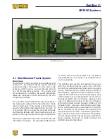
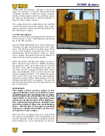
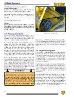
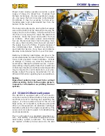
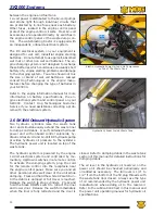
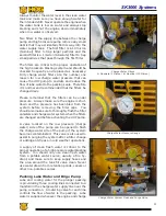
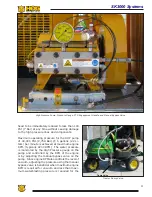
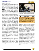
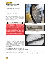
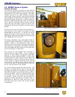
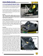
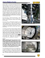
Manual Bypass Valve and Rupture Disc. Note Rupture Disc
Pressure Rating Label on Top of Rupture Disc Assembly
Rupture Disc Label
Summary of Contents for Stripe Hog SK3000
Page 1: ...3 K Operations Manual...
Page 2: ...2...
Page 14: ...14 THIS PAGE WAS LEFT BLANK INTENTIONALLY...
Page 62: ...62 THIS PAGE WAS LEFT BLANK INTENTIONALLY...
Page 77: ...77 Component Repair HOG TECHNOLOGIES...
Page 79: ...79 Component Repair HOG TECHNOLOGIES...
Page 81: ...81 Component Repair HOG TECHNOLOGIES...
Page 82: ...82 NOTES...
Page 83: ...83 JETSTREAM UHP PUMP FLUID END Drawings and Schematics Appendix A HOG TECHNOLOGIES...
Page 86: ...86 THIS PAGE WAS LEFT BLANK INTENTIONALLY...
Page 90: ...90 THIS PAGE WAS LEFT BLANK INTENTIONALLY...
Page 92: ...92 THIS PAGE WAS LEFT BLANK INTENTIONALLY...
Page 104: ...104 THIS PAGE WAS LEFT BLANK INTENTIONALLY...
Page 107: ...107...

