31
SK3000 Systems
Important:
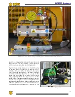
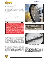
Make sure the drain valve is closed, the
canister door seal is clean and the door is
properly latched before operating the vacu-
um system. The system will not be able to
develop enough vacuum if the canister door
is not sealed and latched or the drain valve
is open.
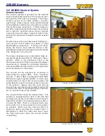
It is normal for some water to travel to the vacuum
filter canister, therefore, it should be drained each
time the waste tank is drained or at least once
every 2 hours of operation. Remember that
excessive water in the canister can pass
through the filter and cause severe damage
to the blower. Always make sure the PTO
clutch is disengaged to stop the vacuum
blower before draining the filter canister and
always close the drain valve when draining
is complete.
Vacuum Hoses
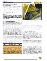
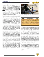
The primary, 6” vacuum hose runs from the cutoff
ball valve connection on top of the waste tank to
the vacuum hose connection on the vacuum filter
canister. Another 4” debris suction vacuum hose
runs from the debris inlet elbow on the top of the
waste tank to the boom assembly on the skid.
The hose is equipped with a quick connector at the
boom end that allows additional 4” vacuum hoses
to be added that connect to the tractor vacuum
hose or other Waterblasting equipment. The
SK3000 can provide enough vacuum and water
pressure to operate Waterblasting equipment up
to 400’ from the skid unit.
Consistent and proper vacuum is important to the
proper operation of the vacuum system. Debris
buildup, kinks, damage or leaks will cause a re-
duction in vacuum at the blasting head, reducing
the efficiency of the operation or cause operations
to stop completely. Many problems with vacuum
hoses are caused by damage or kinks. You should
avoid tight bends and maximize the radius of all
hose curves to minimize the chance of a kink. It
is very important to protect the hoses from con-
tact with sharp objects, abrasive surfaces, foot
or wheel traffic and to inspect the hoses daily to
insure there is no damage or kinks.
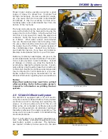
The inside walls of vacuum debris suction hoses
develop wear points caused from the high velocity
of abrasive debris traveling inside the hoses. The
wear points are most prevalent in the outside ra-
dius of tight bends near the blast head and where
the debris hose rises to connect to the boom on
the skid unit. The life of the hoses in these areas
can be extended by rotating the hoses 120
o
once
each week.
Some types of debris will buildup on the inside
walls of the vacuum debris suction hoses to the
point where it restricts debris flow in the system
and reduces vacuum at the blast head. Debris
buildup inside the hoses can be removed by tap-
ping the outside walls with a dead blow ham-
mer while the system is operating at maximum
vacuum. This will flex the hose walls and cause
the debris to break off and be sucked into the
waste tank.
Damaged areas can be repaired by cutting out the
damaged area and splicing in new hose. Tempo-
rary repairs can be made using duck tape.
Vacuum/Waste Tank
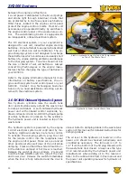
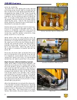
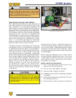
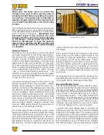
The vacuum/waste tank is constructed from stain
-
less steel panels that provide corrosion resistance
and low maintenance. There is a stainless steel
cutoff ball valve that automatically shuts off the
vacuum flow if the tank becomes full, protect
-
ing the blower system. This valve reduces the
possibility of excessive water from damaging
the blower. If the cutoff ball valve shuts off the
vacuum flow, the vacuum relief valve will auto
-
matically open and reduce the vacuum to near 0
to prevent damage to the vacuum system.
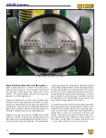
A special filter bag (debris bag) is mounted on
retaining hooks near the top a special stainless
steel liner in the waste tank. The vacuum system
creates vacuum in the tank and debris mixed with
water from the Hog Head and vacuum intake hose
flows directly into the debris bag where solid de
-
bris and particles over 100 microns are trapped.
The filtered water exits the filter bag and flows
Vacuum/Waste Tank
Summary of Contents for Stripe Hog SK3000
Page 1: ...3 K Operations Manual...
Page 2: ...2...
Page 14: ...14 THIS PAGE WAS LEFT BLANK INTENTIONALLY...
Page 62: ...62 THIS PAGE WAS LEFT BLANK INTENTIONALLY...
Page 77: ...77 Component Repair HOG TECHNOLOGIES...
Page 79: ...79 Component Repair HOG TECHNOLOGIES...
Page 81: ...81 Component Repair HOG TECHNOLOGIES...
Page 82: ...82 NOTES...
Page 83: ...83 JETSTREAM UHP PUMP FLUID END Drawings and Schematics Appendix A HOG TECHNOLOGIES...
Page 86: ...86 THIS PAGE WAS LEFT BLANK INTENTIONALLY...
Page 90: ...90 THIS PAGE WAS LEFT BLANK INTENTIONALLY...
Page 92: ...92 THIS PAGE WAS LEFT BLANK INTENTIONALLY...
Page 104: ...104 THIS PAGE WAS LEFT BLANK INTENTIONALLY...
Page 107: ...107...

