background image

50 


FireNET FN-DAC Digital Alarm Communicator I & O Manual - v 1.0 


Section 5 – Testing, Troubleshooting and Maintenance 


After the FN-DAC installation and programming are complete, the system must be 
tested for proper operation.   
 

NOTE:  

Follow NFPA testing methods and frequencies as outlined in the National Fire 

Alarm Code (NFPA 72). 

 
The FN-DAC communicator will report all panel and network events to the monitoring 
station, based on network interface configuration and programming of the report 
groups.  When there is an event to be reported, the FN-DAC will seize the phone line, 
dial the programmed number, report the event(s), and then disconnect.  Events are 
reported by priority, with Fire and Waterflow events being reported first.  Note that at 
times, more than one call may be generated to report an event or series of events.  
 
To test the system, generate an event on the FireNET panel or network.  Each event 
will be reported, based on programming of the FN-DAC.  Confirm receipt of all reports 
with your monitoring station.   


Troubleshooting – 
 

Comms Phone Line 1 (or 2) Trouble 

– The indicated phone line is not being detected 

by the communicator. 
 

  Use a voltmeter to check the voltage on the phone line.  A normal phone line 

will measure approximately 48 VDC.   


Caution

: The voltage present during ringing for an incoming call can be over 100 

volts AC.  Use caution when measuring phone line voltages.  


  Check to be sure that the incoming phone line is correctly connected to the 

L1T and L1R (or L2T and L2R) line connections.  See Figure 2.2.4. 


  Check wiring of the RJ31X jack(s).  Be sure that the FN-DAC is connected 

for proper line seizure. 


Comms Fail # 

- The communicator is unable to report to the monitoring station 

receiver.  The number indicates the account that failed. 
 

  Confirm that the monitoring station telephone number is correct in the 

program. 


  Verify that the correct communication format is selected (Contact ID or SIA). 

firealarmresources.com

Summary of Contents for FireNET FN-DAC

Page 1: ...N DAC Digital Alarm Communicator I O Manual v 1 0 FireNET FN DAC Digital Alarm Communicator Installation and Operation Manual Version 1 0 Created 10 02 07 Updated 02 13 08 Part 1700 10370 firealarmres...

Page 2: ...4 2 5 2 Phone Line Supervision 25 2 5 3 Report Groups 25 2 5 4 Communication Failure 27 2 5 5 AC Fail Reporting 27 Section 3 Programming 28 3 1 FireNET Front Panel Programming 28 3 2 Loop Explorer Pro...

Page 3: ...plorer Remote Diagnostics and Upload Download Capability Full Phone Line Supervision Programmable Dialing Format Tone Pulse or Both Programmable Daily Test Report Interval Quick Installation in FireNE...

Page 4: ...revent the alarm control from reporting a fire Notification Systems All fire alarm systems require notification devices including sirens bells horns and or strobes In residential applications each aut...

Page 5: ...density If such density levels are not created by a developing fire at the location of the detector the detector will not go into alarm 4 Smoldering vs Flaming Fires Smoke detectors even when working...

Page 6: ...cohol or drugs or people on medication or sleeping pills Strobes Strobes can under certain circumstances cause seizures in people with conditions such as epilepsy Drills Studies have shown that certai...

Page 7: ...and will not function property unless they are maintained and tested regularly Alarm is Not Substitute for Insurance While installing a fire alarm system may make the owner eligible for a lower insura...

Page 8: ...jacks that are Part 68 compliant See Installation Instructions for details The REN is used to determine the quantity of devices that may be connected to the telephone line Excessive RENs on the telep...

Page 9: ...sted immediately after installation and periodically thereafter according to the testing instruction found in the installation manual Caution In order for alarm dialing equipment to be able to seize t...

Page 10: ...or is compatible with the following Digital Alarm Communicator Receivers DACR Silent Knight 9500 Contact ID and SIA formats DSC System 3 Contact ID and SIA formats Bosch D6600 Contact ID and SIA forma...

Page 11: ...Ribbon Cable Ribbon Cable Mounting Clips 4 10 mm Standoffs 4 for use when installing the FN DAC in the FN LCD N Network Annunciator 2 2 Installing the FN DAC in the FireNET Panel The FN DAC communicat...

Page 12: ...terminals 18 and 19 should be used to supply power Be sure to observe proper polarity Figure 2 2 2 Power Terminals on FN DAC Communicator 3 Connect the ribbon cable to the J2 plug on the FN DAC commu...

Page 13: ...Power Limited and high voltage wiring Non Power Limited in the FireNET enclosure High voltage wiring locations are circled above telephone lines and AC power input The telephone line connections must...

Page 14: ...RJ31X jacks and the FN DAC terminal block DO NOT USE WIRE OTHER THAN 26 AWG NOTE To ensure proper connection to the Public Switched Telephone Network RJ31X jacks must be installed UL Listed RJ31X jack...

Page 15: ...that the FN DAC is connected only to Loop Start telephone lines NOTE Wiring is to be routed away from sharp projections corners and internal components 5 This completes the installation of the commun...

Page 16: ...unciator enclosure NOTE As with all electronic components the circuit board is very sensitive and can be damaged by electrostatic discharge 2 Connect 24 VDC operating power to the J7 connector on the...

Page 17: ...any private telephone system at the protected premise See Figure 2 2 5 NOTE 26 AWG wire must be used between the RJ31X jacks and the FN DAC terminal block DO NOT USE WIRE OTHER THAN 26 AWG NOTE To ens...

Page 18: ...ireNET panel auxiliary power the power wiring MUST be enclosed within conduit or equivalently protected against mechanical injury 6 If the FN LCD N is being powered by a remote power supply be sure to...

Page 19: ...ected BL Battery Low AC PF AC Failure GF Ground Fault CT Power Supply Trouble Note that the digital inputs must be used with normally open dry contacts The inputs are activated by connecting the negat...

Page 20: ...20 FireNET FN DAC Digital Alarm Communicator I O Manual v 1 0 Figure 2 3 3 Typical Power Supply Connections firealarmresources com...

Page 21: ...21 FireNET FN DAC Digital Alarm Communicator I O Manual v 1 0 Figure 2 3 4 Typical Power Supply Connections firealarmresources com...

Page 22: ...C Digital Alarm Communicator I O Manual v 1 0 7 This completes the installation of the communicator Reconnect power to the annunciator See section 3 of this manual for programming instructions fireala...

Page 23: ...olarity J3 Telephone Line Connections L1T Phone Line 1 Tip Supervised L1R Phone Line 1 Ring Supervised P1T House Telephone Line 1 Tip P1R House Telephone Line 1 Ring L2T Phone Line 2 Tip Supervised L2...

Page 24: ...ommunicator cannot report events successfully using phone line 1 it automatically switches to phone line 2 Account 1 and account 2 are used together for primary and backup reporting If duplicate repor...

Page 25: ...rmal line voltage Each line is checked every 10 seconds If trouble with a phone line is detected the FireNET display will indicate the trouble condition The phone line failure can be communicated to t...

Page 26: ...ent Reset Event Backup Report Account 2 and 4 Only Account 2 and 4 can be selected to report to the associated phone number as a backup of the primary account For this feature account 1 is considered...

Page 27: ...r the Comms Fail trouble from the panel display press the panel Reset button This action will also generate a communication restore event that will be reported to the monitoring station 2 5 5 AC Fail...

Page 28: ...127 Installation and Operation Manual part number 1700 09948 1 Install the communicator as described in Section 2 2 of this manual 2 From the Access Level 3 Menu select Edit Configuration and then sel...

Page 29: ...isplay Select Edit Accounts Attributes to begin the programming See step 8 in this section to program the Test Report Time 5 Select the account you wish to configure from the list 6 Select the option...

Page 30: ...ata Valid characters are 0 9 B F Note that only the first four digits are reported in Contact ID format Up to 6 digits may be used with SIA format NOTE For correct communicator operation always enter...

Page 31: ...programming is complete press the Exit button NOTE By default all report groups are selected for all four accounts Therefore account 2 is the Backup account for account 1 and account 4 is the backup...

Page 32: ...ime The test report will be sent every 24 hours at the time selected Press the Enter button when the desired time is displayed 10 This completes the programming of the dialer Please note that the dial...

Page 33: ...art number 1700 09948 The FN DAC communicator can be added to any panel or network annunciator on the network Double click on the Dialer icon to add the dialer to the selected panel After it has been...

Page 34: ...ith UL and NFPA standards the FN DAC dialer may not be programmed to call a telephone number that is call forwarded to the DACR Dialing You may select Tone Pulse or Both If Both is selected the FN DAC...

Page 35: ...ease see Appendix C for more details on zone and address reporting Account 1 4 tabs Select the account you wish to program Account Number Enter the account number for this location Valid characters ar...

Page 36: ...A Backup Report Check this box to enable backup reporting You must also select the events that you want to be reported to the backup destination as shown above Backup Report is only available on Accou...

Page 37: ...display board PC port and the dialer J2 in order to load the Loop Explorer program into the panel Be sure that you reconnect the dialer to the PC port as soon as the programming download in Loop Expl...

Page 38: ...nd Operation Manual part number 1700 09948 4 1 Getting Connected 4 1 1 Setting the modem COM Port In order to dial in to the FN DAC you must select the correct modem COM port in Loop Explorer 1 From t...

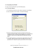
Page 39: ...the number of the phone line that is connected to the phone line 1 terminals on the FN DAC dialer Note that only phone line 1 on the FN DAC is configured to answer an incoming call and establish the r...

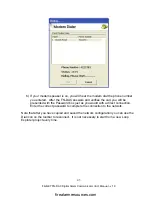
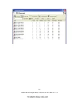
Page 40: ...d and click on the Connect button Loop Explorer will search the network for all panels and network annunciators After the search is complete you will see the Communications window You are now connecte...

Page 41: ...project in Loop Explorer 2 Add a panel to the site It is important that the panel added be the same type and same address as the panel that the FN DAC is installed in at the jobsite 2 loop panel 4 loo...

Page 42: ...phone line that is connected to the phone line 1 terminals on the FN DAC dialer When the correct number has been entered click on the OK button Save the project by clicking on the Save button on the...

Page 43: ...es the call you will be presented with the Password box just as you would with a direct connection Enter the correct password to complete the connection to the network Note that after you have copied...

Page 44: ...irect serial connection To copy the configuration from the network put a check in the Sync box for each panel you wish to copy Note that the arrows in the direction column are pointed toward the Panel...

Page 45: ...alues You may copy view and save the event log and analog values from the panels on the network Establish a connection to the network and then click on the appropriate tab Select the panel you wish fr...

Page 46: ...46 FireNET FN DAC Digital Alarm Communicator I O Manual v 1 0 firealarmresources com...

Page 47: ...el you wish to view from the pull down menu and then click on the Start button You will see the information displayed on the panel To view a different panel click on the Stop button select another pan...

Page 48: ...ed to program a complete new installation or to assist service personnel with minor programming changes as necessary NOTE If you are sending a configuration to a newly installed system ensure that the...

Page 49: ...n select Edit Dialer Choose Set Remote Configuration from the Edit Dialer menu Use the up or down arrow keys to enable the option and then press the Enter button After the remote configuration option...

Page 50: ...the FireNET panel or network Each event will be reported based on programming of the FN DAC Confirm receipt of all reports with your monitoring station Troubleshooting Comms Phone Line 1 or 2 Trouble...

Page 51: ...Interface configuration LEDs The Green LED LED 2 flashes to indicate that the communicator is receiving power and data During normal operation this LED will flicker At times it will not be lit but it...

Page 52: ...te and try to call again This will allow time for the FN DAC to report the pending event s o If you have just disconnected from the FN DAC wait for approximately 30 seconds before calling again After...

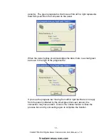
Page 53: ...nel replies or acknowledges the data there is a small green bar seen to the right of the progress bar If you see the progress bar moving from left to right but there is no reply from the panel indicat...

Page 54: ...or I O Manual v 1 0 Loop Explorer Messages 1 Status No Dial Tone this indicates that there is no dial tone at the computer modem Check the phone line connection to the modem and ensure that the line i...

Page 55: ...established If the FN DAC is answering the call and you get this error repeatedly it may be helpful to decrease the number of rings before the FN DAC answers You should also confirm that there is no...

Page 56: ...ection to the panel was lost perhaps due to noise on the phone line or the call being interrupted Try to make the call again If you continue to have this trouble at a particular site check the phone l...

Page 57: ...active alarms in progress you may connect again 6 This message indicates that the call was disconnected before entering the password This may be due to noise on the phone line Try to connect again If...

Page 58: ...icator I O Manual v 1 0 8 The error shown above will display when trying to send a program if the Set Remote Configuration option has not been enabled at the panel Please see Section 4 2 5 for details...

Page 59: ...e and contains no user serviceable parts Follow testing methods and frequencies as outlined in the National Fire Alarm Code NFPA 72 for Digital Alarm Communicator Transmitters DACT If service is requi...

Page 60: ...orting summary list below The activation and restore use the same event code but with the appropriate modifier For example a Low Battery report is 1 302 or E302 and the restore to normal is 3 302 or R...

Page 61: ...abled Fire Drill FI FK 604 Fire Drill Button Pressed on Panel Fire Routing Trouble FT FJ 320 Trouble on Fire Routing Circuit on Panel Ground Fault YP YQ 310 Ground on External Panel Wiring Loop Explor...

Page 62: ...S SR 200 ATG ALG AIE ALG DH AMS Action Auxiliary UA UH 140 FRCME DIMM CZM1 Action Silence FL FL 406 FRCME DIMM CZM1 Action Reset OR OR 313 FRCME DIMM CZM1 Supervised Loop Trouble FT FJ 373 FRCME DIMM...

Page 63: ...t _____ Alarms _____ Alarm Restore _____ Supervisory Trouble Enable Disable _____ Service Test _____ System Reset Account Number 2 ____________ Phone Number 2 _____________ Report _____ Alarms _____ A...

Page 64: ...es of zone reporting are Multiple input modules for example DIMM can report individual inputs by zone Inputs and outputs can be assigned or grouped into zones as determined and defined by the system d...

Page 65: ...dvantages of address reporting are May be more suitable for large multi panel reporting when using Contact ID Less programming time may be required as devices do not need to be assigned to zones for r...

Page 66: ...lace equipment which has been repaired by others abused improperly installed altered or otherwise misused or damaged or exposed to conditions outside the products specifications in any way Unless prev...

Reviews: