16
FireNET FN-DAC Digital Alarm Communicator I & O Manual - v 1.0
2.3 Installing the FN-DAC in the FN-LCD-N Network Annunciator
The FN-DAC communicator may also be installed in the FN-LCD-N Network
Annunciator.
NOTE
: All connections must be made while power is disconnected to the FN-LCD-N to
avoid damage to the equipment!
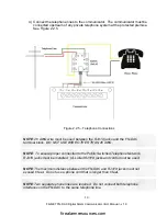
1) Before installing the FN-DAC circuit board, screw the supplied 10 mm standoffs
into the mounting holes in the back of the FN-LCD-N annunciator enclosure.
Next,
carefully install the communicator circuit board in the enclosure using the
mounting screws. The circuit board must be mounted in the accessory module
location using the standoffs provided with the FN-DAC. Note that the circuit
board must be installed with the telephone line connections toward the top of
the annunciator enclosure.
NOTE
: As with all electronic components, the circuit board is very sensitive and can be
damaged by electrostatic discharge.
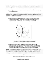
2) Connect 24 VDC operating power to the J7 connector on the communicator.
The AUX 24 VDC terminals on the FN-LCD-N Network Annunciator should be
used to supply power. Be sure to observe proper polarity.
NOTE
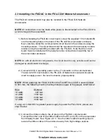
: When powering the FN-LCD-N from the FireNET Aux 24 VDC power (limited
to 500 mA), the following maximum wiring distances apply at the gauges noted below:
Wire
Distance
18 AWG
925 feet
16 AWG
1500 feet
14 AWG
2400 feet
12 AWG
3900 feet
If using a UL 864/1481 regulated power supply to power the FN-LCD-N, please see
step 5 below.
3) Connect the ribbon cable to the J2 plug on the FN-DAC communicator.
Connect the other end of the ribbon cable to the PC port (J5) on the annunciator
front display board. See Figure 2.2.3. Use the ribbon cable mounting clips to
secure the ribbon cable in the enclosure away from high voltage sources.
firealarmresources.com

