2 Control Functions
Control of Master/Slave group
SMGB0120 rev.0 - 11/2017
40
2.3 Control of Master/Slave group
2.3.1 Summary of control of Master/Slave group
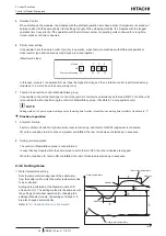
In addition to the operation as a single chiller unit, this product allows the operation of multiple chiller units as a single
heat source system.
1
Features
•
The function to control the Master/Slave group comes equipped as standard, and thus an exclusive controller is not
necessary.
•
It is possible to connect up to 8 modules to 1 group.
•
The modules within 1 group should be set with module number addresses between 1 and 8, and the module
designated as unit 1 controls the number of units
•
There is a mode that determines the number of units in operation from the variations in inlet temperature of the chiller
unit (1-pump system).
2.3.2 Setting method
1
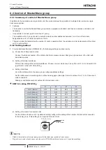
For standard specifications (RCME-WH1), the following settings are done locally.
a.
Connection of transmission wires
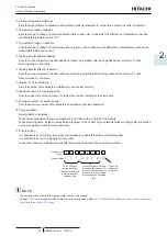
Connect the terminal boards of the chiller units that compose a same chiller group (a maximum of 8 units) with
transmission wires.
b.
Setting of terminal resistance
Perform the setting of the terminal resistance. Choose one unit, which may be any from unit 1 to 8, and switch ON
(up) DSW7-1 of its CPU PCB (PCB
C
).
c.
Setting of address
For all the chiller units in the same group, configure address settings.
Set the addresses in ascending order, without leaving gaps. (Example: Set unit numbers from 1 to 5, if there are 5
units connected).
Missing or duplicated numbers will result in transmission error.
DSW3 of setting PCB (PCB
A
)
#1
#2
#3
#4
Unit 1 (Master)
OFF
OFF
OFF
OFF
Unit 2 (Slave 1)
OFF
OFF
ON
OFF
Unit 3 (Slave 2)
OFF
ON
OFF
OFF
Unit 4 (Slave 3)
OFF
ON
ON
OFF
Unit 5 (Slave 4)
ON
OFF
OFF
OFF
Unit 6 (Slave 5)
ON
OFF
ON
OFF
Unit 7 (Slave 6)
ON
ON
OFF
OFF
Unit 8 (Slave 7)
ON
ON
ON
OFF
d.
Setting of number of connected units
For the chiller unit set as unit 1 by address setting, configure the setting of the number of chiller units connected
to the same group. (This setting is not required for units 2 to 8).
RSW1
Adjust the arrow
to the number
PCB
A
Unit 1 only
?
N O T E
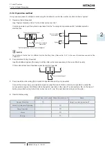
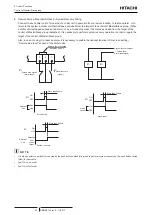
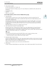
• Refer to the instructions for water piping works for the attachment position of each sensor.
• Plug in the connector of each sensor into the control PCB of the chiller unit set as unit 1 by address settings.


