Hexagon NovAtel MarinePak7 User Manual Download Page 56

Chapter 3   Configure the MarinePak7 Using the LCD UI

After all the configuration options have been set, press the

Enter

button to accept the changes and save

the settings to the receiver.

Press the

Back

button to return to the Network Status screen. Press the

HOME

button to return to the

Position Status screen.
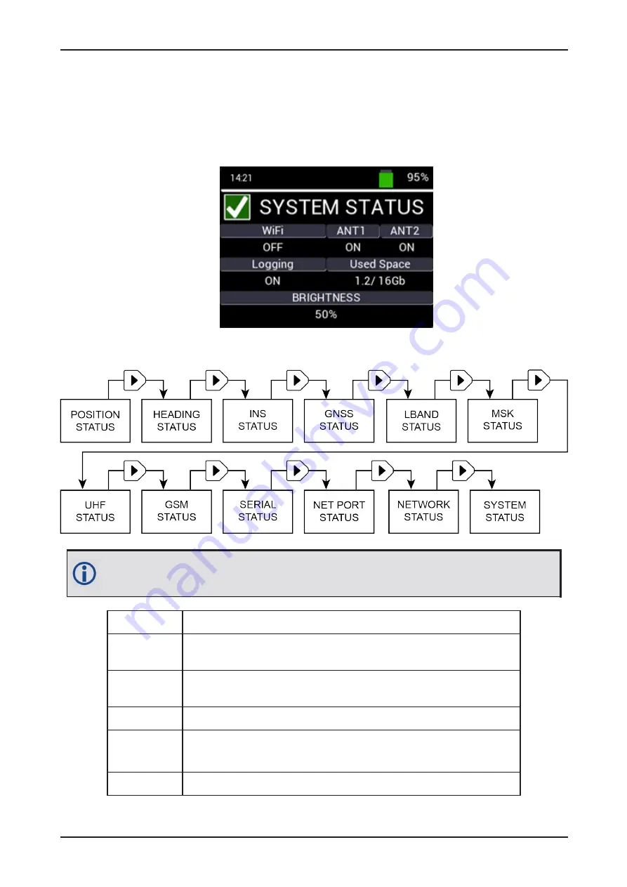
3.13 System Status

To access the System Status screen from the Home screen, press the

Right

button until the System

Status screen displays.

For MarinePak7 models without the UHF module, the GSM Status screen follows the MSK
Status screen.

WiFi

Wi-Fi status (On or Off).

ANT1

LNA DC power (antenna power) status for the GNSS1 port (On or Off).
(For the primary GNSS (RF1) and MSK beacon antenna.)

ANT2

LNA DC power (antenna power) status for the GNSS2 port (On or Off).
(For the secondary GNSS (RF2) antenna.)

Logging

Internal logging status (On or Off).

Used Space

Displays the amount of internal memory used for logging (in GB).

For example,

1.2/16.0

equates to 1.2 GB used out of 16.0 GB available.

Brightness

Shows the LCD lighting intensity (10% to 100%).

MarinePak7 User Manual 2

56

Summary of Contents for NovAtel MarinePak7

Page 1: ...OM 20000188 2 August 2022 MarinePak7 User Manual...

Page 2: ...OEM7 are trademarks of NovAtel Inc entities within the Hexagon Autonomy Positioning division their affiliated entities and or their licensors All other trademarks are properties of their respective o...

Page 3: ...MarinePak7 to AC Power Source 21 2 9 2 Connect the MarinePak7 to a DC Power Source 21 2 9 3 Power on the MarinePak7 21 2 9 4 Power off the MarinePak7 21 2 9 5 MarinePak7 Internal Battery 21 2 10 Cell...

Page 4: ...rd 62 4 3 1 General Status Tile 62 4 3 2 Module Status Tile 63 4 4 GNSS Receiver 63 4 4 1 GNSS Status Tile 63 4 4 2 Position Status Tile 64 4 4 3 INS Status Tile 65 4 4 4 Heading Status Tile 66 4 4 5...

Page 5: ...APPENDIX A MarinePak7 Technical Specifications 100 A 1 MarinePak7 Performance Specifications 101 A 2 MarinePak7 Mechanical Specifications 104 A 3 MarinePak7 Electrical and Environmental Specification...

Page 6: ...23 Figure 5 MarinePak7 UI Screen 26 Figure 6 MarinePak7 Dimensions Top 104 Figure 7 MarinePak7 Dimensions Front 104 Figure 8 MarinePak7 Dimensions Back 105 Figure 9 MarinePak7 Mounting Shroud Tabs 106...

Page 7: ...able 14 MarinePak7 Environmental Specifications 108 Table 15 MarinePak7 Regulatory Compliance 109 Table 16 MarinePak7 RF Input LNA Power Output 109 Table 17 Data Communications Interfaces 110 Table 18...

Page 8: ...OD Global System Mobile Radio GSM MarinePak7 contains a GSM radio with the following approvals l FCC ID XMR201202M95 UHF Radio MarinePak7 contains a UHF Ultra High Frequency radio with the following a...

Page 9: ...obtained from the NovAtel web site at novatel com products novatel compliance eu declaration of conformity Radio Information Description of Service GSM Operational Frequency 900 MHz Uplink 890 915 MHz...

Page 10: ...it to your dealer or supplier at the end of its life The objectives of the European Community s environment policy are in particular to preserve protect and improve the quality of the environment pro...

Page 11: ...Customer Support support novatel hexagon com 3 You can also perform a factory reset of the receiver to clear any unknown settings For information about using the LCD UI to perform a factory reset ref...

Page 12: ...adaptability offers multi constellation multi frequency and size configurations for any application requirement Excellent acquisition and re acquisition times allow this receiver to operate in environ...

Page 13: ...d output l EVENT Input l EVENT Output Screw Terminal Receiver grounding point USB Type A USB Host connector SMA WiFi antenna The USB and WiFi antenna connectors are on the front of the MarinePak7 1 2...

Page 14: ...es text A caution that actions operation or configuration may lead to incorrect or improper use of the hardware A warning that actions operation or configuration may result in regulatory noncompliance...

Page 15: ...ired below for other equipment needed that is not included with the MarinePak7 2 2 Additional Equipment Required For the receiver to perform optimally the following user supplied additional equipment...

Page 16: ...y Power Supply cable US 60723210 US Included Connect the MarinePak7 Power Supply to the mains supply Power Supply Cable 60723211 EU Included Connect the MarinePak7 Power Supply to the mains supply Ext...

Page 17: ...s not exceeding 10 0 dB If the limit is exceeded excessive signal degradation may occur and the receiver may not meet performance specifications NovAtel offers several coaxial cables to meet GNSS ante...

Page 18: ...ing the GNSS Antenna on the next page for more information 2 Mount MarinePak7 in the desired location Refer to Mounting the MarinePak7 on the next page for more information 3 Use a coaxial cable to co...

Page 19: ...rce Refer to Connect Power to the MarinePak7 on page 21 for information about other powering options 12 Briefly press the button on the front of the MarinePak7 to power up the receiver When the receiv...

Page 20: ...maintenance 2 8 2 Ceiling Mount The MarinePak7 is shipped with the mounting shroud installed on the top of the MarinePak7 In this position the MarinePak7 can be secured to a flat surface such as a sh...

Page 21: ...VDC 1 Connect a cable with a 4 pin LEMO connector on one end to the DC connector on the MarinePak7 2 Connect the other end of the cable to a DC power source that provides 12 to 24 VDC 3 Connect the v...

Page 22: ...r source is restored Replacing the Internal Battery The MarinePak7 must only be used with the Inspired Energy ND2037HD34 battery pack A replacement battery assembly can be purchased from your NovAtel...

Page 23: ...e Battery SIM card cover 2 Remove lithium battery from the compartment if installed 3 Insert the SIM card into position 4 Replace lithium battery if available and replace the Battery SIM card cover 5...

Page 24: ...ith external data communications equipment such as computers and data loggers The Ethernet port supports IPv4 Internet layer TCP IP transport ping and connection from a Telnet client Users can conduct...

Page 25: ...Pak7 which operates in the 410 475 MHz and 902 928 MHz bands This radio is typically used to receive RTK correction data The UHF radio configuration can be viewed and modified from the LCD UI see UHF...

Page 26: ...Keypad Button Description Right Button Press to advance the UI status screen to the next screen Press to select a configuration parameter Left Button Press to return to the previous status screen Pre...

Page 27: ...er off the MarinePak7 3 2 Position Status The Position Status Home screen displays the position status of the MarinePak7 Position Status Indicator Icon displays GREEN when the receiver reports SOLUTIO...

Page 28: ...unreliable PENDING When a FIX position command is entered the receiver computes its own position and determines if the fixed position is valid PENDING implies there are not enough satellites currently...

Page 29: ...carrier phase ambiguities L1_INT Single frequency RTK solution with carrier phase ambiguities resolved to integers WIDE_INT Multi frequency RTK solution with carrier phase ambiguities resolved to wid...

Page 30: ...VERGING solution INS_PPP INS position where the last applied position update used a converged Oceanix PPP PPP solution 3 2 1 Position Configuration To access Position configuration from the Position S...

Page 31: ...e configured using the LCD UI You must use the MarinePak7 Web User Interface to configure the NTRIP mount point settings See NTRIP Tile on page 75 Press the Enter button on the keypad to apply the new...

Page 32: ...titude is 90 to 90 degrees Longitude Use the Up and Down buttons to change the longitude of the MarinePak7 The value range for the longitude is 180 to 180 degrees Height MSL Use the Up and Down button...

Page 33: ...ess the Enter button to enable EDIT MODE Use the arrow buttons to change the configuration Press the Enter button to save the configuration Heading Offset The Heading Offset parameter is used to add a...

Page 34: ...he Home screen press the Right button 2 times SPAN Status Indicator Displays GREEN when a SPAN solution has been computed Displays RED when a valid SPAN solution is not available Azimuth Left handed r...

Page 35: ...s for the SPAN installation Antenna X Axis Y Axis Z Axis 1 Primary Antenna Offset from the IMU center of navigation to the phase center of the primary GNSS antenna Offset from IMU to primary GNSS ante...

Page 36: ...offset from IMU 100 to 100 m 3 5 GNSS Status The GNSS Status screen provides information about the GNSS solution To access the GNSS Status screen from the Position Status Home screen press the Right...

Page 37: ...ration settings Move to the parameter that is to be configured and press the Enter button to enable EDIT MODE Use the arrow buttons to change the configuration Press the Enter button to save the confi...

Page 38: ...he received L band signals To access the LBAND Status screen from the Home screen press the Right button until the LBAND Status screen displays LBAND Status Indicator Displays GREEN when there is a va...

Page 39: ...have received data in the last 30 seconds SEARCH At least one decoder is receiving data and is searching for the format LOCKED At least one decoder has locked onto the format 3 6 1 LBAND Configuration...

Page 40: ...the L band frequency This option is only available when the tracking mode is set to MANUAL Press the Enter button to enable frequency input Use the Left or Right buttons to select the required digit...

Page 41: ...status screen provides the status of the MSK beacon module To access the MSK Status screen from the Home screen press the Right button until the MSK Status screen displays Status Indicator Displays g...

Page 42: ...c MSK search mode Manual Manual tune mode Requires manual frequency tuning Frequency This option is only available when MANUAL mode is selected Press the Right or Left button to change the value of th...

Page 43: ...age 30 This screen display the status of the UHF radio module To access the UHF Status screen from the Home screen press the Right button until the UHF Status screen displays Status Indicator Displays...

Page 44: ...ompatibility Mode Use the Left and Right buttons to select the UHF radio modem protocol Compatibility Mode Protocol Modulation Link Rate bps Channel Spacing kHz FEC 0 PacCrest GMSK 4800 12 5 ON 1 PacC...

Page 45: ...z After the configuration options have been set press the Enter button to accept the changes and save the settings to the receiver Press the Back button to return to the UHF Status screen or press the...

Page 46: ...dels without the UHF module the GSM Status screen follows the MSK Status screen Signal Power Displays the signal strength of the received cellular signal Mode Displays the cellular connection mode GPR...

Page 47: ...meters are available for each serial port Serial Line Standard Displays the COM port line standard RS232 RS422 Baud Rate Displays the COM port baud rate Serial Protocol Settings Displays the COM port...

Page 48: ...figuration Line Standard Use the Left or Right button to select RS232 or RS422 as the COM port line standard default RS232 Baud Rate Use the Left or Right button to select the baud rate used by the CO...

Page 49: ...C IMU is connected to the port IMU IMU Rover Select when a SPAN IMU IMU is connected to the port INS OUT Rover Outputs INS messages CMR IN Rover Accepts CMR corrections External Source RTCMV3 IN Rover...

Page 50: ...the INS message selection option Use the Left or Right button to scroll through the INS messages available Select the required message and press the Enter button to access message output rate options...

Page 51: ...ys For MarinePak7 models without the UHF module the GSM Status screen follows the MSK Status screen The following parameters are available for each ICOM port Protocol The protocol used by the ICOM por...

Page 52: ...port mode UDP IP Address Use the Left or Right button to set the UDP IP address TCP UDP Port Use the Left or Right button to set the TCP UDP port Rx or Tx Protocol Use the Left or Right button to sele...

Page 53: ...dent 50 Hz and 100 Hz messages are available only for INS Output INS Messages When you select INS OUT as the output protocol you need to choose the INS messages and data output rate When INS OUT is hi...

Page 54: ...us screen displays the status of the receiver s network connection To access the Network Status screen from the Home screen press the Right button until the Network Status screen displays For MarinePa...

Page 55: ...ns to move between digits Use the Up and Down buttons to change the value of each digit Press the Enter button to save the IP Address and return to Network Config screen Netmask The Netmask is only co...

Page 56: ...s screen displays For MarinePak7 models without the UHF module the GSM Status screen follows the MSK Status screen WiFi Wi Fi status On or Off ANT1 LNA DC power antenna power status for the GNSS1 port...

Page 57: ...Press the Enter button to access the On and Off option 3 Press the Left or Right button to make a selection On Enables WiFi Off Disables WiFi 4 Press the Enter button to confirm the selection ANT1 1...

Page 58: ...of the receiver press the Enter button A confirmation screen appears l To confirm and initiate a factory reset press the Enter button l To cancel a factory reset press the Back button Delete Logs 1 P...

Page 59: ...ates are input into the Base Station Configuration on page 31 screen The correction source type and baud rate must first be set while receiver is in ROVER mode After all the configuration options have...

Page 60: ...he UHF module the GSM Status screen follows the MSK Status screen Model Displays the purchased firmware model of the OEM7720 GNSS receiver Software Displays the MarinePak7 software version Firmware Di...

Page 61: ...tion The MarinePak7 SSID is printed on a label on the side of the receiver The format of the SSID is MarinePak7 Receiver PSN e g MarinePak7 ABCDEF1234567 A prompt for a password will appear The defaul...

Page 62: ...when the receiver has successfully locked onto at least 1 beam Displays red when the receiver has failed to lock onto at least 1 beam If the L band status icon is red check that you have a valid PPP O...

Page 63: ...valid correction source Displays red when the MSK module is not active or not locked onto a valid correction source GSM Displays green when the GSM cellular modem is active Display red when the GSM c...

Page 64: ...GLO Satellites Number of GLONASS satellites used in the solution BDS Satellites Number of BeiDou satellites used in the solution GAL Satellites Number of Galileo satellites used in the solution HDOP H...

Page 65: ...ther than SOL_COMPUTED is reported from the receiver Accuracy 2D The horizontal standard deviation RMS Accuracy Height The vertical standard deviation RMS Satellites The number of satellites used in t...

Page 66: ...g Status Tile The Heading Status tile displays the current ALIGN Heading solution Heading Status A green circle in the top right corner indicates GNSS Heading status is healthy A red circle indicates...

Page 67: ...are version of the GNSS receiver board in the format P R Where P hardware platform R hardware revision Example OEM7720 1 01 Model Firmware model loaded on the GNSS receiver board 4 4 6 Receiver Config...

Page 68: ...he Correction Format drop menu select the correction format used NOVX NOVATELX correction format RTCMV3 RTCMV3 RTK correction format RTCMV2 RTCMV2 DGPS correction format MSK only CMR CMR correction fo...

Page 69: ...DPOS To configure the MarinePak7 as an RTK Rover receive RTK corrections 1 Click the Edit icon to enter the configuration window 2 Click the Enabled drop down menu and select Rover 3 Click the Save ch...

Page 70: ...he longitude is 180 to 180 degrees 5 In the Height MSL field enter the height of the MarinePak7 relative to mean sea level The value range for the height is 1000 to 20000000 metres For the Latitude Lo...

Page 71: ...arameters 1 In the Lever Arm 1 text boxes enter the offsets from the IMU center of navigation to the phase center of the primary GNSS antenna The range for the Lever Arm 1 offsets is 100 to 100 metres...

Page 72: ...m the IMU body frame The second box is the Y axis rotation offset from the IMU body frame The third box is the Z axis rotation offset from the IMU body frame 4 In the Position Offset text boxes enter...

Page 73: ...lar offset to be added to heading output The range is 180 to 180 degrees 2 Click the Save changes button 4 4 10 PPS Tile The PPS tile displays the polarity setting for the PPS signal Click the Edit ic...

Page 74: ...Generates a normally high active low pulse with the falling edge as the reference POSITIVE Set the polarity of the PPS pulse to positive Generates a normally low active high pulse with the rising edge...

Page 75: ...the MarinePak7 3 In the Gateway box enter the IP address for the Gateway used by the MarinePak7 4 Click the DHCP drop menu and select the DHCP mode used by the MarinePak7 Select ON to enable DHCP and...

Page 76: ...vice 4 In the Password box enter the password for the NTRIP service 5 Click the Mount Point drop menu and select the mount point of the NTRIP service 6 Click the Save changes button 4 5 L Band The L b...

Page 77: ...AUTO Only one beam ID is displayed when a beam is manually selected For each beam tracked the real time C No dB Hz levels of the transmission beams are shown below the beam ID 4 5 2 L Band Details Ti...

Page 78: ...is a ranking of granted access L band beams in the order they appear in the stored beam table see LBAND Configuration on page 39 for the available beams Manual The receiver assigns the specified beam...

Page 79: ...active and locked onto a UHF channel Displays red when the UHF module is inactive or not locked onto a UHF channel Signal Strength Received UHF signal strength Mode UHF radio mode Protocol UHF radio p...

Page 80: ...io compatibility mode See the compatibility mode descriptions in the following table 3 Click the Frequency drop menu and select the frequency used by the radio module 4 Click the Save changes button C...

Page 81: ...K 9600 25 0 ON 11 PacCrest GMSK 9600 25 0 OFF 12 PacCrest 4FSK 19200 25 0 ON 13 PacCrest 4FSK 19200 25 0 OFF 14 PacCrest FST 4FSK 19200 25 0 ON 15 PacCrest FST 4FSK 19200 25 0 OFF 16 Trimtalk GMSK 960...

Page 82: ...onto a valid correction source Signal Strength The Signal to Noise Ratio of the signal being received by the MSK module Station The station ID of the DGPS corrections source being received Frequency...

Page 83: ...frequency Manual Mode only 4 8 Serial Ports The Serial Ports page displays the serial port configuration and the logs configured to be output from the selected serial ports These parameters can also b...

Page 84: ...on this COM port RS422 Use RS422 protocol on this COM port Baud rate 2400 4800 9600 19200 38400 57600 115200 230400 460800 Select the baud rate used on this COM port Stop Bits 1 Use one stop bit 2 Us...

Page 85: ...Enables direct communication with MarinePak7 via COM1 to COM3 ISA100C ISA100C Rover Select when a SPAN ISA100C IMU is connected to the port IMU IMU Rover Select when a SPAN IMU IMU is connected to th...

Page 86: ...ser Interface To add a log to output click the Add icon to open the Add Log Configuration window To modify a log being output click the Edit icon to open the Edit Log Configuration window MarinePak7 U...

Page 87: ...For the list of the logs available see Table 8 NMEA Message IDs below and Table 9 INS Message IDs on the next page Period Hz 1 2 5 10 20 50 100 200 Enter the frequency in Hertz at which the log is ou...

Page 88: ...HVE SPAN Heave message PVA SPAN INSPVA message PRH SPAN PASHR NMEA Inertial Attitude Data TSS SPAN TSS1 Protocol for Heave Roll and Pitch Table 9 INS Message IDs 4 9 Net Ports This page displays the I...

Page 89: ...menu and select the message protocol used for this ICOM port NMEA OUT Output NMEA message types INS OUT Output INS message types CONFIG Enables direct communication with OEM7 GNSS receiver via ICOM p...

Page 90: ...o output click the Add icon to open the Add Log Configuration window To modify a log being output click the Edit icon to open the Edit Log Configuration window To remove a log from the Log List click...

Page 91: ...z messages is Receiver Model dependent 50 Hz 100 Hz and 200 Hz message are available only for INS output messages 4 10 Logging The Logging tab provides information about the internal data storage and...

Page 92: ...download the logs stored on internal data storage or delete stored logs from internal data storage To download the logs 1 Insert a USB stick into the USB port on the front of the MarinePak7 2 Click th...

Page 93: ...lect Log File to Delete window appears 2 Click the drop down menu and select the log file to delete 3 Click the Delete button A confirmation window appears 4 Click the Delete button 4 10 5 Log List Th...

Page 94: ...erface To modify a log being saved to internal storage click the Edit icon for the log to change to open the Edit Log Configuration window To remove a log from the Log List click the Delete icon Marin...

Page 95: ...EM7_Core_Logs htm Use the ONTIME trigger only for NMEA logs Period 1 2 5 10 20 50 100 200 If the ONTIME Trigger is selected enter the frequency in Hertz at which the log is output Availability of the...

Page 96: ...ANT1 tile is used to enable or disable antenna power to the GNSS1 antenna port on the MarinePak7 This port is used for the primary GNSS antenna input and the MSK beacon input To enable antenna power...

Page 97: ...is not active Signal Strength Displays the signal strength of the cellular reception Mode Displays the cellular connection mode Operator Displays the cellular network operator 4 11 6 Screen The Screen...

Page 98: ...are To update the firmware on the MarinePak7 1 Obtain the new firmware file by downloading the firmware file from novatel com support support materials firmware download 2 Copy the firmware file to th...

Page 99: ...Chapter 4 Web User Interface 6 Click the Open button 7 Click the Install button Once the upload is complete the MarinePak7 will restart MarinePak7 User Manual 2 99...

Page 100: ...page l MarinePak7 Mechanical Specifications on page 104 l MarinePak7 Electrical and Environmental Specifications on page 108 l MarinePak7 Data Communications Specifications on page 110 l MarinePak7 St...

Page 101: ...er Performance 1Typical values All position and velocity RMS values are based on Horizontal position accuracy Performance specifications are subject to GNSS system characteristics Signal in Space SIS...

Page 102: ...5 Time to First Fix Hot 19 s almanac and recent ephemeris saved and approximate position and time entered Cold 40 s no almanac or ephemeris and no approximate position or time Signal Reacquisition 0 5...

Page 103: ...mm B2I 4 cm 0 5 mm B2a 3 cm 0 5 mm B2b1 3 cm 0 5 mm ALIGN Heading Accuracy Baseline 2 m 0 08 degrees Baseline 4 m 0 05 degrees Heave Performance2 Instantaneous Heave 5 cm or 5 Delayed Heave 3 5 cm or...

Page 104: ...ns Top below l Figure 7 MarinePak7 Dimensions Front below l Figure 8 MarinePak7 Dimensions Back on the next page l Figure 9 MarinePak7 Mounting Shroud Tabs on page 106 l Figure 10 MarinePak7 Mounting...

Page 105: ...APPENDIX A MarinePak7 Technical Specifications Figure 8 MarinePak7 Dimensions Back MarinePak7 User Manual 2 105...

Page 106: ...APPENDIX A MarinePak7 Technical Specifications Figure 9 MarinePak7 Mounting Shroud Tabs MarinePak7 User Manual 2 106...

Page 107: ...APPENDIX A MarinePak7 Technical Specifications Figure 10 MarinePak7 Mounting Holes MarinePak7 User Manual 2 107...

Page 108: ...mber ND2037HD34 Type Rechargeable Lithium Ion Voltage nominal 7 2 V Capacity nominal 6 8 Ah Energy nominal 49 0 Wh Discharge current maximum 8 A Discharge power maximum 38 4 W Length maximum 151 30 mm...

Page 109: ...5 dB to 40 dB 26 dB typical HDR enabled 20 dB to 40 dB 30 dB typical RF Input Frequencies GPS L1 GPS L2 GPS L5 1575 42 MHz 1227 60 MHz 1176 45 MHz GLONASS L1 GLONASS L2 GLONASS L3 1593 1610 MHz 1237 1...

Page 110: ...r 460800 bit s Default 9600 Signals supported COM2_Tx COM2_Rx RS 232 COM2_Tx COM2_Tx COM2_Rx COM2_Rx RS 422 Port DB9 male COM3 Electrical format RS 232 RS 422 Data rates1 2400 4800 9600 default 19200...

Page 111: ...ates Hi speed 480 Mb s Port USB Type A ETHERNET Physical layer 10BASE T 100BASE TX Port RJ45 WiFi WiFi module Texas Instruments WL1835MOD Band 2400 MHz Transmission power max 0 0549 W Security WPA2 En...

Page 112: ...t Active low Programmable variable frequency outputs ranging from 0 Hz to 50 MHz These outputs are configured using the EVENTOUTCONTROL command PPS Output Active low A time synchronization output This...

Page 113: ...ion time 2 seconds typical Impedance 50 Output protocol RTCM SC 104 NMEA 0183 Table 20 Receiver Module A 7 GSM Specifications GSM module Quectel M95 Bands US 850 1900 MHz Transmission power 850MHz max...

Page 114: ...ceiver Module A 9 MarinePak7 Connectors The following tables provide the pinouts for the MarinePak7 connectors A 9 1 COM Ports RS 232 RS 422 Pin Signal Name Description Pin Signal Name Description 1 E...

Page 115: ...l Name Description Pin Signal Name Description 1 EVENTIN2 Input mark for which a pulse greater than 150 ns triggers certain logs to be generated 1 EVENTIN2 Input mark for which a pulse greater than 15...

Page 116: ...eceive data positive 3 TxD Transmit data 3 TxD Transmit data positive 4 NC No connection 4 NC No connection 5 GND Signal ground 5 GND Signal ground 6 NC No connection 6 NC No connection 7 RTS Request...

Page 117: ...served 5 Reserved Reserved 6 GND Signal ground 7 EVENTOUT4 Programmable variable frequency output ranging from 0 Hz to 50 MHz 8 EVENTIN1 Input mark for which a pulse greater than 150 ns triggers certa...

Page 118: ...Cable This cable connects a device with a DB9 serial port such as a computer to the COM1 COM2 or COM3 port on the MarinePak7 Figure 11 Serial Data Cable DB9 J1 DB9 J2 2 3 3 2 4 1 6 5 5 1 6 4 7 8 8 7...

Page 119: ...Supply The Power Supply connects the MarinePak7 to the mains supply The connector on the mains supply side of the Power Supply varies depending on the region in which the Power Supply is intended to b...

Page 120: ...lying Lead Wire Color 1 Power Black 2 Power Red 3 GND Blue 4 GND White Table 29 DC Power Cable Pinout The fuse holder contains a 4 A fuse which is detailed in the following table Fuse Type Specificati...

Page 121: ...MarinePak7 User Manual 2 121...

Reviews: