background image

HAULOTTE GROUP 


DECAL KIT - AU ............................................................................................................................ 88


IDENTIFICATION PLATES & OPTIONAL EQUIPMENT – AU...................................................... 90


7 OPTIONAL EQUIPMENT..................................................................................................................93


DRIVE AND SET ........................................................................................................................... 94


MATERIAL LIFT HOOK ................................................................................................................. 97


PLATFORM ROTATOR............................................................................................................... 100


8  MATERIAL SAFETY ......................................................................................................................101


LEAD ACID BATTERIES, WET, FILLED WITH ACID – UN 2794............................................... 101


POWERFLOW™ AW HVI HYDRAULIC OIL ............................................................................... 106


9  AXLE AND RELATED COMPONENTS .........................................................................................113


9A DEXTER AXLE AND RELATED COMPONENTS.........................................................................113


SET UP AND ADJUSTMENT......................................................................................................... 113


HOW TO USE YOUR ELECTRIC BRAKES PROPERLY.................................................................. 117


MAINTENANCE........................................................................................................................... 118


STORAGE ................................................................................................................................... 130


TROUBLE SHOOTING................................................................................................................ 132


9B  BRADLEY BRAKE ADJUSTMENT..............................................................................................136


AERIAL WORK PLATFORMS WITH STANDARD BRAKES ...................................................... 136


THIRTEEN PERCENT (13 %) GRADE TEST ............................................................................. 138


AERIAL WORK PLATFORMS WITH DRIVE AND SET BRAKES............................................... 139


TROUBLESHOOTING THE BRADLEY RUNNING GEAR .......................................................... 140


INSPECTION FORM FOR HAULOTTE AERIAL WORK PLATFORMS ............................................141


LIST OF TABLES 


TABLE 1-1.  MINIMUM SAFE APPROACH DISTANCES .....................................................................9


TABLE 1-2.   BEAUFORT SCALE .......................................................................................................12


TABLE 4-1.  BATTERY CHARGER FAULT CODES ...........................................................................39


TABLE 4-2.  TROUBLE SHOOTING....................................................................................................55


TABLE 4-3  ERROR CODE DEFINITIONS..........................................................................................56


TABLE 4-4.  ERROR CODE DEFINITIONS - MOTOR CONTROLLER ..............................................67


TABLE 9-1.  WHEEL TORQUE REQUIREMENTS............................................................................116


TABLE 9-2.  TRAILER WIRE SIZE CHART.......................................................................................117


TABLE 9-3.  MAINTENANCE SCHEDULE ........................................................................................118


TABLE 9-4.  RECOMMENDED WHEEL BEARING LUBRICATION SPECIFICATIONS...................124


TABLE 9-5.  TIRE WEAR DIAGNOSTIC CHART ..............................................................................128


TABLE 9-6.  MAGNET AMPERES CHART .......................................................................................129


TABLE 9-7.  TROUBLESHOOTING – HYDRAULIC BRAKING SYSTEM.........................................133


TABLE 9-8.  TROUBLESHOOTING - ELECTRIC BRAKING SYSTEM.............................................135


Summary of Contents for 3522A

Page 1: ...OPERATOR S MAINTENANCE MANUAL B33 01 0093 Rev 4 May 2013...

Page 2: ...that only trained and authorized personnel attempt to operate and maintain the aerial work platform This manual shall be considered a permanent and necessary component of the aerial work platform and...

Page 3: ...QUIPMENT MAINTENANCE 37 BATTERY RECHARGE 38 BATTERY FAULT CODES 39 DAILY SERVICE CHECKS 40 WEEKLY SERVICE CHECKS 43 MONTHLY SERVICE CHECKS 44 ANNUAL SERVICE CHECKS 45 STRUCTURAL INSPECTION 47 MOTOR DR...

Page 4: ...TEST 138 AERIAL WORK PLATFORMS WITH DRIVE AND SET BRAKES 139 TROUBLESHOOTING THE BRADLEY RUNNING GEAR 140 INSPECTION FORM FOR HAULOTTE AERIAL WORK PLATFORMS 141 LIST OF TABLES TABLE 1 1 MINIMUM SAFE...

Page 5: ...sed 48 Figure 4 12 Ground Lower Control Panel for Leveling System 49 Figure 4 13 Platform Position 50 Figure 4 14 Ground Lower Control Panel for Overload Protection 50 Figure 4 16 Manual Outrigger Con...

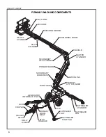
Page 6: ...IB LIFT CYLINDER SLAVE CYLINDER PRIMARY BOOM SECONDARY LIFT CYLINDER TURNTABLE PRIMARY HITCH TRAILER WHEEL JACK COUPLER DOLLY REST BOOM RELEASE LATCH INTERFACE PLATE AXLE GENERATOR CYLINDER OUTRIGGER...

Page 7: ...e use of intelligence and common sense is the best practice when following any safety policy LEGEND SAFETY ADVISORIES The following safety advisories are used throughout this manual to indicate specif...

Page 8: ...m that has any known or suspected defect ALWAYS comply with the instructions found in Safety and or Service Bulletins distributed by the manufacturer factory Bulletins may contain critical procedures...

Page 9: ...only on surfaces that can support a pressure of 25 psi 1 8 kg cm2 to ensure safe operation ALWAYS keep personnel away from potential pinch and shear points and from potential crush hazards as indicat...

Page 10: ...tform from a position on a truck bed trailer floating vessel or scaffolding without written approval from the manufacturer factory NEVER operate the Drive function if equipped on grades exceeding 4 5...

Page 11: ...to the wind may affect the aerial work platform stability NEVER attach overhanging loads when raising or lowering the platform NEVER use the boom or platform to push or pull or to lift any part of the...

Page 12: ...reeze Raises dust and loose paper small branches are moved 13 17 20 28 5 5 7 9 5 Fresh Breeze Small trees in leaf begin to sway crested wavelets form on inland waterways 18 24 29 38 8 0 10 7 6 Strong...

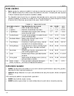
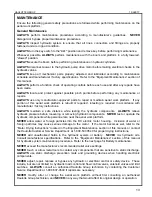
Page 13: ...tance while testing the hydraulic components ALWAYS relieve hydraulic pressure before loosening or removing hydraulic components NEVER test or operate the hydraulic components while personnel are near...

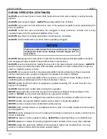
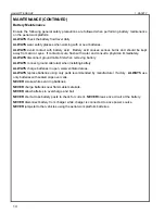
Page 14: ...WAYS disconnect ground cable first when removing battery ALWAYS connect ground cable last when installing battery ALWAYS charge batteries in open well ventilated areas ALWAYS replace batteries using o...

Page 15: ...ment and on machine options Only one boom function is permitted at a time this function is only operable as long as the boom is within the safe operating zone Once a boom motion exceeds its safe opera...

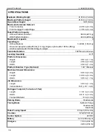
Page 16: ...tions add 150 lbs 68 kg to weight Turntable Rotation 700 Non Continuous Leveling Capability 12 5 Platform Dimensions Height 3 ft 7 in 1 1 m Length 2 ft 6 in 0 8 m Width 4 ft 0 in 1 2 m Platform Rotati...

Page 17: ...sec Secondary Down Fast 18 22 sec Secondary Down Slow 62 66 sec Boom Jib Jib Up Fast 16 10 sec Jib Up Slow 12 16 sec Jib Down Fast 10 14 sec Jib Down Slow 26 30 sec Extension Boom Boom Extend Fast 10...

Page 18: ...ited to engines tires and batteries which may be part of the product are not manufactured or warranted by Haulotte Any applicable warranty for such component is provided through the original manufactu...

Page 19: ...he time the parts order is placed 3 Replacement parts will then be sent by Haulotte Group BilJax to the dealer or distributor All parts are invoiced at dealer distributor list price Credits will be is...

Page 20: ...isual structural damage or when there is suspected internal structural damage Haulotte Group may require that the aerial work platform be returned to our facility for a complete inspection and recerti...

Page 21: ...rs boom lift elevation and rotation functions The platform upper control panel only controls boom lift elevation and rotation NOTE The elevation and rotation controls are operational only when the out...

Page 22: ...except emergency lowering Removal of the KEY protects against any unauthorized persons attempting to operate the aerial work platform The KEY may be removed with the KEY SWITCH 1 in any selected posi...

Page 23: ...e will raise the secondary boom Pressing pushing and holding a desired SPEED 15 button and the SECONDARY BOOM DOWN 12 button at the same time will retract the secondary boom Pressing pushing and holdi...

Page 24: ...r extension retraction of all four 4 outriggers Select the EXTEND 21 button or RETRACT 22 button and the AUTO LEVEL 23 button at the same time To individually extend or retract the outriggers Select t...

Page 25: ...gure 3 2 Figure 3 2 Platform Upper Control Panel 1 2 Engine Start and Choke Glow Plug Models with Engines Only Start a cold engine by pressing pushing and holding the CHOKE 2 button and pressing pushi...

Page 26: ...ies are recharged 5 Emergency Stop Button When pushed in the EMERGENCY STOP 5 button disconnects electrical power to the ground lower and platform upper control panels The EMERGENCY STOP 5 button shou...

Page 27: ...EED 6 button and the JIB BOOM RAISE 13 button at the same time will raise the jib boom pressing pushing and holding a desired SPEED 6 button and the JIB BOOM DOWN 14 button at the same time will lower...

Page 28: ...al work platform is on a firm and level surface and there are no potential hazards such as overhead obstructions or electrically charged conductors DO NOT operate the aerial work platform if such haza...

Page 29: ...ton and the LED at the AUTO LEVEL 23 button will be lit Refer to Figure 3 4 Figure 3 4 Outrigger Control Panel o Auto Level Press push and hold the EXTEND 21 and AUTO LEVEL 23 buttons at the same time...

Page 30: ...ed function button at the same time Become familiar with the location and function of all controls Learn to smoothly START and STOP all boom functions When all aerial work platform operations are comp...

Page 31: ...he proportional valve counterclockwise until it stops and insert pump handle into the pump handle fitting Manual Retraction Begin manual retraction or rotation by turning the proportional valve counte...

Page 32: ...ete electrical power failure a load shift or any other emergency The booms may be lowered in any order but the logical order would be The PRIMARY boom first The SECONDARY boom next The JIB boom last T...

Page 33: ...e parking brake is disengaged When the parking brake is engaged it is parallel with the tongue tube when disengaged it is perpendicular to the tongue The trailer tires are adequately and evenly inflat...

Page 34: ...y that the coupling is secure NOTE If using the jack raises the bumper of the tow vehicle 2 3 inches the ball hitch coupling is secure Release the PARKING BRAKE by rotation the handle down until it is...

Page 35: ...e designated crane fork lift pockets B Follow all crane operating instructions as indicated by the crane manufacturer When using a forklift use only the designated forklift pockets B Follow all forkli...

Page 36: ...ailer Chock B the wheels and apply the PARKING BRAKE Place a wooden block C under the TONGUE near the TRAILER HITCH Lower the TONGUE JACK DOLLY WHEEL D until the TRAILER TONGUE rests on the wooden blo...

Page 37: ...Department at 1 800 537 0540 or visit Haulotte Group online at www haulotte usa com if additional information is needed Critical or suspect areas identified during any scheduled inspection of the aer...

Page 38: ...the output of the battery charger and may extend charge time Plug the EXTENSION CORD into outlet Verify that the GREEN CHARGING indicator LED is lit on the BATTERY CHARGER FACEPLATE Refer to Figure 4...

Page 39: ...ULT CODES Code Description Limits Cause F0 No Battery 10 volts Loose connection or battery missing F1 Over Voltage 112 charge voltage Connected to wrong battery voltage F2 Over Current 60 amperes Oper...

Page 40: ...rol Panel Error Code definitions TABLE 4 3 ERROR CODE DEFINITIONS is located later in this section If the MOTOR CONTROLLER S green light is flashing there is an error refer to the Motor Controller Err...

Page 41: ...ach outrigger Raise all outriggers until the footpads are not in contact with the ground Verify that all outrigger status LEDs on the ground lower control panel are unlit Lower one outrigger until the...

Page 42: ...uge add clean Hydraulic Fluid while all booms are in the stowed down position and the outriggers are fully retracted and in the stowed upright position Pour slowly to avoid creating air pockets in the...

Page 43: ...n and seal with proper materials Inspect transport hitch components for damage Applicable to trailer mounted aerial lift platforms only Inspect the aerial work platform for missing loose or damaged ha...

Page 44: ...ocated in the Axle and Related Components section of this manual for more detailed information Verify that the Level Sensor is operating correctly Fully deploy outriggers until all outrigger LEDs and...

Page 45: ...played by simultaneous pressing pushing the RABBIT 2 and the TURTLE SPEED 3 buttons on the ground lower control panel and reading the DISPLAY PANEL 1 Refer to Figure 4 5 Figure 4 5 Display Run Time Ho...

Page 46: ...e 4 6 Figure 4 6 Machine Position for Slew Ring Measurement Measure the distance between the slew ring gear and the horizontal plate above using a 2 in 50 mm caliper or bore micrometer Refer to Figure...

Page 47: ...ork performed and environmental conditions o The inspection and maintenance record of the aerial work platform o The effectiveness of all controls and components o A visual inspection of the aerial wo...

Page 48: ...ions Be aware that the LED s on the top of the sensor will need to be observed the Max Tilt Level Exceeded LED is red and the TILT OK LED is green Press push and hold the SET ZERO button located on th...

Page 49: ...5 buttons and the OUTRIGGER EXTEND 6 button on the ground lower control panel simultaneously and holding for 5 seconds 3 Scroll through the maintenance menu using the TURTLE 7 button to scroll down u...

Page 50: ...er to Figure 4 13 Figure 4 13 Platform Position 2 Use the ground lower control panel to access the control box maintenance menu Refer to Figure 4 14 Figure 4 14 Ground Lower Control Panel for Overload...

Page 51: ...the OUTRIGGER EXTEND 6 button on the ground lower control panel simultaneously and holding for 5 seconds o Scroll through the maintenance menu using the TURTLE 7 button to scroll down use the RABBIT 8...

Page 52: ...rm a test of all functions including brake functions before commissioning or reselling the aerial work platform Always repair or replace all damaged or malfunctioning components before commissioning o...

Page 53: ...s manual if necessary Procedure to raise the outriggers manually Disconnect the outrigger s wire harness from the lower control lower box Refer to Figure 4 17 Plug it into the receptacle on the Manual...

Page 54: ...performing as expected The female quick disconnect is attached to the Hydraulic Power Unit at the TP1 port Refer to Figure 4 19 The Pressure Gauge is composed of B02 00 0064 Pressure Gauge that measu...

Page 55: ...to error code definitions Table 3 3 Outrigger indicator LED lights do not function a Key switch turned to the OFF or platform controls position b EMERGENCY STOP engaged c Outriggers not deployed a Tur...

Page 56: ...wer up This is a latched error Power must be cycled to clear error The Platform Control Engine On LED will also blink a 1 blink error code 006 DRIVE CONTROL HAS STUCK KEY Drive Control has detected a...

Page 57: ...om functions Overload Boom This is a latched error Power must be cycled to clear error Machines with Load Sense option only 020 LOSS OF LOAD CELL CONNECTION Load Sense Module has lost connection with...

Page 58: ...when Extend circuit was energized Use a piece of wire to short the Extend coil This is a latched error Power must be cycled to clear error Checked only at power up 035 OPEN CIRCUIT RETRACT A load of l...

Page 59: ...ched error Power must be cycled to clear error Checked only at power up 050 SHORTED CIRCUIT OUTRIGGER RETRACT Excessive load was detected when Outrigger Retract circuit was energized Use a piece of wi...

Page 60: ...s a latched error Power must be cycled to clear error Not Tested Do not want to crank engine on power up 065 OPEN CIRCUIT ENGINE CHOKE A load of less than 70mA was detected when Engine Choke circuit w...

Page 61: ...error Checked only at power up Machines with Drive option only 081 OPEN CIRCUIT DRIVE ENABLE A load of less than 70mA was detected when Drive Enable circuit was energized Disconnect a wire from Drive...

Page 62: ...up Machines with 4WD option only 095 OPEN CIRCUIT REVERSE 2 C28 A load of less than 70mA was detected when Reverse 2 C28 circuit was energized Disconnect a wire from Reverse 2 C28 coil This is a latch...

Page 63: ...h RPM to a value less than 3000 RPM and attempt to drive This is a latched error Power or engine must be cycled to clear error Machines with 4WS option only 121 OPEN CIRCUIT BRAKE FWS C21 A load of le...

Page 64: ...cled to clear error Checked only at power up Machines with 4WS option only 135 OPEN CIRCUIT DC D FWS C28 A load of less than 70mA was detected when DC D FWS C28 circuit was energized Disconnect a wire...

Page 65: ...ion only 150 SHORTED CIRCUIT FWS R2 Excessive load was detected when FWS R2 circuit was energized Use a piece of wire to short the FWS R2 coil This is a latched error Power must be cycled to clear err...

Page 66: ...y at power up Machines with 4WS option only 163 OPEN CIRCUIT FWS PROP A2 A load of less than 70mA was detected when FWS Prop A2 circuit was energized Disconnect a wire from FWS Prop A2 coil This is a...

Page 67: ...operating normally None required 1 11 Configuration Range Error One or more controller personality settings are out of range Use Sevcon calibrator to enter correct settings from latest Personality She...

Page 68: ...l If fault repeatedly occurs look for binding on the hydraulic cylinders or sticking valves Otherwise the pump motor may be failing 8 3 Pump I 2 T Current Limit Cutback Maximum power available to pump...

Page 69: ...e at www haulotte usa com MASTER SLAVE CYLINDER REPLACEMENT Use the following procedure to remove and replace faulty cylinders Master Cylinder Refer to Figure 5 1 for the location of this cylinder Wit...

Page 70: ...nd the telescoping boom until there is adequate exposure of the pin retainer and pivot pin approximately 2 ft 0 7 m Verify that the upper boom is supported by lifting straps and an overhead hoist or e...

Page 71: ...lic cylinders Refer to Figure 5 3 for the location of these cylinders Figure 5 3 Location of Manual Lowering Valves Press push in and hold the emergency lowering valve button on the lift cylinder to r...

Page 72: ...ic hoses from the cylinder Elevate hoses to prevent leakage Plug or cap exposed hose fittings and cylinder ports At the base of the cylinder unbolt and remove the pin retainer from each side of the pi...

Page 73: ...ylinder unbolt and remove the pin retainer from each side of the pivot pin Place a block of wood shoring between the outrigger tube and the cylinder Remove the pivot pin using a hammer and a brass or...

Page 74: ...using an overhead hoist and lifting straps or equivalent Replace or reinstall the cylinder by following the above instructions in the reverse order of removal Actuate the hydraulic system and check f...

Page 75: ...ion that is required for the safe and proper use of the aerial work platform Decals should be considered necessary components of the machine and should be checked before each use to verify that they a...

Page 76: ...HAULOTTE GROUP 6 DECAL REPLACEMENT 76 DECAL KIT ANSI...

Page 77: ...17 B06 00 0534 Decal Warning Platform Operation Articulating 1 18 B06 00 0062 Decal Notice AC Power 2 19 B06 00 0530 Decal Air 120 PSI 2 20 B06 00 0531 Decal Water 3000 PSI 2 21 B06 00 0552 Decal Not...

Page 78: ...HAULOTTE GROUP 6 DECAL REPLACEMENT 78 IDENTIFICATION PLATES OPTIONAL EQUIPMENT ANSI...

Page 79: ...Manual Rotation Option 1 44 B06 00 0527 Decal Warning Drive and Set Drive and Set Option 1 45 B06 00 0528 Decal Notice Drive and Set Drive and Set Option 1 46 B06 00 0553 Decal Warning Jockey Wheel Dr...

Page 80: ...HAULOTTE GROUP 6 DECAL REPLACEMENT 80 DECALS ANSI 0202 0523 B06 00 0161B B06 00 0530 B06 00 0531 B06 00 0471 B06 00 0484 B06 00 0034 B06 00 0482 B06 00 0521 B06 00 0538 B06 00 0535 3522A HTA 13 P...

Page 81: ...HAULOTTE GROUP 6 DECAL REPLACEMENT 81 DECALS ANSI CONTINUED B06 00 0533 B06 00 0505 B06 00 0534 B06 00 0404...

Page 82: ...LACEMENT 82 DECALS ANSI CONTINUED B06 00 0037 B06 00 0552 B06 00 0544 B06 00 0475 B06 00 0551 B06 00 0405 B06 00 0550 B06 00 0542 B06 00 0495 B06 00 0481 B06 00 0477 B06 00 0543 B06 00 0478 B06 00 049...

Page 83: ...NT 83 DECALS ANSI CONTINUED B06 00 0528 B06 00 0547 B06 00 0487 B06 00 0485 B06 00 0474 B06 00 0062 B06 00 0497 B06 00 0486 B06 00 00068 B06 00 0403 B06 00 0473 B06 00 0503 B06 00 0529 B06 00 0488 B06...

Page 84: ...HAULOTTE GROUP 6 DECAL REPLACEMENT 84 DECAL KIT CE...

Page 85: ...6 B06 00 0538 CE Decal HTA 13 P Black Clear Vinyl with Black Letters 2 7 B06 00 0537 CE Decal Notice Range of Motion 3522A 2 B06 01 4021 DU DECAL KIT Dutch Includes the following B06 01 4021 EN DECAL...

Page 86: ...HAULOTTE GROUP 6 DECAL REPLACEMENT 86 IDENTIFICATION PLATES OPTIONAL EQUIPMENT CE...

Page 87: ...R DESCRIPTION QTY 29 B06 00 0529 Decal Notice Platform Rotate Manual Rotation Option 1 30 B06 00 0527 Decal Warning Drive and Set Drive and Set Option 1 31 B06 00 0528 Decal Notice Drive and Set Drive...

Page 88: ...HAULOTTE GROUP 6 DECAL REPLACEMENT 88 DECAL KIT AU...

Page 89: ...CE Decal Caution Compartment Access 2 20 B06 00 0572 CE Decal Caution Read Parts and Service Manual 1 21 B06 00 0034 CE Decal Danger Battery Charger Safety 2 24 B06 00 0496 CE Decal Caution Generator...

Page 90: ...HAULOTTE GROUP 6 DECAL REPLACEMENT 90 IDENTIFICATION PLATES OPTIONAL EQUIPMENT AU...

Page 91: ...otice Platform Rotate Manual Rotation Option 1 31 B06 00 0527 Decal Warning Drive and Set Drive and Set Option 1 32 B06 00 0528 Decal Notice Drive and Set Drive and Set Option 1 33 B06 00 0530 Decal A...

Page 92: ...HAULOTTE GROUP 6 DECAL REPLACEMENT 92...

Page 93: ...tments or modifications or otherwise alter the equipment in any way that is not expressly recommended by the manufacturer When operating an aerial work platform equipped with optional components obser...

Page 94: ...ted in the stowed upright position NEVER drive the aerial work platform without the operator fully secured inside the platform NEVER operate the Drive function on grades exceeding 4 5 This optional fe...

Page 95: ...triggers can be deployed and or retracted from either the ground lower or platform upper control panel on aerial work platforms with the Drive and Set Option 8 Platform Position LED When the PLATFORM...

Page 96: ...UST be in its fully lowered stowed position before moving Press push and hold the DRIVE ENABLE button on the platform lower control panel move the JOYSTICK in the desired direction The Aerial work pla...

Page 97: ...rd from the cord wrap on the platform Disconnect the platform upper control box s PLUG from the LOAD SENSE MODULE located on the PLATFORM MOUNT Refer to Figure 7 2 Figure 7 2 Disconnect Plug from Load...

Page 98: ...E located on the PLATFORM MOUNT NOTE If the loopback plug is not inserted into the Load Sense the Emergency Stop circuit will not be complete and the aerial work platform will not function Firmly secu...

Page 99: ...nual WARNING ALWAYS observe the manufacturer s weight lifting limitations when using the material lifting hook ALWAYS use lifting straps or wire rope slings that are rated at a minimum 500 lbs lifting...

Page 100: ...tator turn the rotator handle in the direction of desired rotation clockwise or counterclockwise Motion continues in the desired direction until rotator handle is released or the platform reaches a sa...

Page 101: ...22A HTA 13 P Articulating Boom Lift as well as any potential health and safety hazards related to these chemicals Material Safety Data Sheets are included here in accordance with applicable federal an...

Page 102: ...HAULOTTE GROUP 8 MATERIAL SAFETY 102 MATERIAL SAFETY DATA SHEET LEAD ACID BATTERIES WET FILLED WITH ACID UN 2794 CONT...

Page 103: ...HAULOTTE GROUP 8 MATERIAL SAFETY 103 MATERIAL SAFETY DATA SHEET LEAD ACID BATTERIES WET FILLED WITH ACID UN 2794 CONT...

Page 104: ...HAULOTTE GROUP 8 MATERIAL SAFETY 104 MATERIAL SAFETY DATA SHEET LEAD ACID BATTERIES WET FILLED WITH ACID UN 2794 CONT...

Page 105: ...HAULOTTE GROUP 8 MATERIAL SAFETY 105 MATERIAL SAFETY DATA SHEET LEAD ACID BATTERIES WET FILLED WITH ACID UN 2794 CONT...

Page 106: ...HAULOTTE GROUP 8 MATERIAL SAFETY 106 MATERIAL SAFETY DATA SHEET POWERFLOW AW HVI HYDRAULIC OIL...

Page 107: ...HAULOTTE GROUP 8 MATERIAL SAFETY 107 MATERIAL SAFETY DATA SHEET POWERFLOW AW HVI HYDRAULIC OIL CONTINUED...

Page 108: ...HAULOTTE GROUP 8 MATERIAL SAFETY 108 MATERIAL SAFETY DATA SHEET POWERFLOW AW HVI HYDRAULIC OIL CONTINUED...

Page 109: ...HAULOTTE GROUP 8 MATERIAL SAFETY 109 MATERIAL SAFETY DATA SHEET POWERFLOW AW HVI HYDRAULIC OIL CONTINUED...

Page 110: ...HAULOTTE GROUP 8 MATERIAL SAFETY 110 MATERIAL SAFETY DATA SHEET POWERFLOW AW HVI HYDRAULIC OIL CONTINUED...

Page 111: ...HAULOTTE GROUP 8 MATERIAL SAFETY 111 MATERIAL SAFETY DATA SHEET POWERFLOW AW HVI HYDRAULIC OIL CONTINUED...

Page 112: ...HAULOTTE GROUP 8 MATERIAL SAFETY 112 MATERIAL SAFETY DATA SHEET POWERFLOW AW HVI HYDRAULIC OIL CONTINUED...

Page 113: ...ted 2 at 3 000 mile 4 828 Kilometers intervals 3 or as use and performance requires The brakes should be adjusted in the following manner 1 Jack up trailer and secure on adequate capacity jack stands...

Page 114: ...djusting tool may be necessary 4 Then rotate the star wheel in the opposite direction until the wheel turns freely with a slight lining drag 5 Replace the adjusting hole cover and lower the wheel to t...

Page 115: ...er to determine the appropriate torque lever for your wheels However you must not exceed the limits of the wheel mounting studs on the axles It is extremely important to apply and maintain proper whee...

Page 116: ...ft lb 122 162 N m 16 5 x 6 75 20 25 ft lb 27 34 N m 50 60 ft lb 68 81 N m 90 120 ft lb 122 162 N m 16 5 x 9 75 55 60 ft lb 75 81 N m 120 125 ft lb 162 169 N m 175 225 ft lb 237 305 N m 14 5 Demont Tig...

Page 117: ...ed by road testing Brake lockup grabbiness or harshness is quite often due to the lack of synchronization between the tow vehicle and toe trailer being towed too high of a threshold voltage over 2 vol...

Page 118: ...for Leaks Sticking Brake Lines Inspect for Cracks Leaks and Kinks Trailer Brake Wiring Inspect Wiring for Bare Spots Fray etc Breakaway System Check Battery Charge and Switch Operation At Every Use H...

Page 119: ...n replacing your magnets BREAK CLEANING AND INSPECTION Your trailer brakes must be inspected and serviced immediately if a loss of performance is indicated With normal use servicing at one year interv...

Page 120: ...exter Axle offers several types of bearing arrangements and lubrication methods Dexter s standard wheel bearing configuration consists of opposed tapered roller bearing cones and cups fitted inside of...

Page 121: ...February of 2002 a new type of retainer is used Gently pry off retainer from the nut and set aside 5 Unscrew the spindle nut counterclockwise and remove the spindle washer 6 Remove the hub from the s...

Page 122: ...heel bearing cavities are clean and free of contamination before reinstalling bearing and seals The presence of these contaminants will cause premature wheel bearing failure BEARING INSPECTION Wash al...

Page 123: ...at this while rotating the bearing from roller to roller 4 Continue this process until you have the entire bearing completely filled with grease 5 Before reinstalling apply a light coat of grease on t...

Page 124: ...alvoline Durablend Great Plans Lubricants Lithium Complex EP 2 Chem Arrow Arrow 2282 Oil SAE 90 SAE 80W 90 SAE 75W 90 Approved Oil Sources Ashland Oil Valvoline Durablend Valvoline Power Lube CITGO Pe...

Page 125: ...ghtening the spindle nut to approximately 50 ft lb 68 N m 12 30 cm wrench or pliers with full hand force 2 Then loosen the spindle nut to remove the torque DO NOT rotate the hub 3 Finger tighten the s...

Page 126: ...ature it is imperative that the seals be replaced BEFORE bearing lubrication Otherwise the chance of grease getting on brake linings is greatly increased BEARING REPLACEMENT AND DRUM INSTALLATION 1 On...

Page 127: ...due to trailer weight distribution use the tire rated for the heaviest wheel position NOTE The capacity rating molded into the sidewall of the tire is not always the proper rating for the tire if used...

Page 128: ...nual The threshold voltage of a controller is the voltage applied to the brakes when the controller first turns on Lower threshold voltage will provide for smoother braking If the threshold voltage is...

Page 129: ...size 4 Broken wires 5 Blown fused fusing of brakes is not recommended 6 Improperly functioning controllers or resistors Another common electrical problem is shorted or partially shorted circuits indi...

Page 130: ...our wheels periodically every 2 3 weeks during periods of prolonged storage AFTER PROLONGED STORAGE INSPECTION PROCEDURE Before removing trailer from jack stands 1 Remove all wheels and hubs or brake...

Page 131: ...e up to date 2 Check hitch Is it showing wear Is it properly lubricated 3 Fasten safety chains and breakaway switch actuating chain securely Make certain the breakaway battery is fully charged 4 Inspe...

Page 132: ...echanic Typical problems in a hydraulic braking system are Air or vacuum leaks Hydraulic system leaks Air in brakes lines Water or other impurity in brake fluid Rusted or corroded master or wheel cyli...

Page 133: ...Automatic Make Several Reverse Stops Harsh Brakes Grease or Fluid on Linings Replace Shoes and Lining Grease or Oil on Linings Clean or Replace Surging Brakes Out of Round Drums or Cracked Drums Machi...

Page 134: ...ts or synchronization adjustments can generally be traced to electrical system failure Voltmeters and ammeters are essential tools for proper troubleshoot of electric brakes Mechanical causes are ordi...

Page 135: ...istor and Synchronize Faulty Controller Test and Correct Broken Wires Repair or Replace Loose Connections Find and Repair Intermittent Brakes Faulty Ground Find and Repair Wrong Magnet Lead Wire Color...

Page 136: ...g of the shoes on the drum 5 Repeat steps 2 4 to adjust the other BRAKE 6 Confirm that the BRAKE CABLES are attached at both ends Each cable has two threaded ends a dished washer and two nuts fitted t...

Page 137: ...HAULOTTE GROUP 9 AXLE AND RELATED COMPONENTS 137 Figure 9 1 Standard Brake Adjustment Procedure...

Page 138: ...the reverse direction to properly set the run away brakes At this point the brakes will lock up the wheels 13 Disengage the brakes if the brakes need to be re adjusted repeat step 10 14 The brakes are...

Page 139: ...Check the end that is connected inside the brake hub first Next confirm that the BALANCE BAR is parallel to the AXLE BODY then check the other end of the BRAKE CABLE it should pass through the CABLE...

Page 140: ...distance between washer and bracket must be set as a constant so that the BRAKE HANDLE can reapply the brake when the bracket is released during drive functions the washer must not interfere with ROD...

Page 141: ...D Inspect hydraulic system and fluid levels D Check battery electrolyte level W Inspect electrical wiring for damaged broken or frayed wires W Inspect transport hitch for damage Applicable for machine...

Page 142: ...Distributed by 125 Taylor Parkway Archbold Ohio 43502 Phone 800 537 0540 419 445 8915 Fax 419 445 0367 www haulotte usa com B33 01 0093 Rev 4 3522A HTA 13 P Operator s Maintenance Manual May 2013...

Reviews: