HAULOTTE GROUP
9 AXLE AND RELATED COMPONENTS
125
MAINTENANCE (CONTINUED)
NOTE:
The convenient lubrication provisions of the E-Z Lube® and the
oil lubrication must not replace periodic inspection of the bearings.
SEAL INSPECTION AND REPLACEMENT
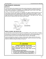
Whenever the hub is removed; inspect the seal to assure that it is not
kicked or torn and is still capable of properly sealing the bearing cavity. If
there is any question of condition, replace the seal. Use only the seals
specified in the Seal Replacement Chart.
To replace the seal:
1. Pry the seal out of the hub with a screwdriver. Never drive the seal
out with the inner bearing as you may damage the bearing.
2. Apply a PERMATEX sealant to the outside of the new seal.
NOTE:
Permatex sealant should not be used on rubber encased seals.
3.
Tap the new seal into place using a clean wood block.
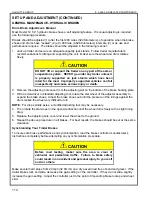
BEARING ADJUSTMENT AND HUB REPLACEMENT
If the hub has been removed or bearing adjustment is required, the following adjustment procedure
must be followed:
1. After placing the hub bearings, washers, and spindle nut back on the axle spindle in reverse order
as detailed in the previous section on hub removal, rotate the hub assembly slowly while
tightening the spindle nut to approximately 50 ft-lb (68 N-m), (12” (30 cm) wrench or pliers with full
hand force.)
2. Then loosen the spindle nut to remove the torque. DO NOT rotate the hub.
3. Finger-tighten the spindle nut until just snug.
4. Back the spindle nut out slightly until the first castellation lines up with the cotter key hole and
insert the cotter pin.
5. Bend over the cotter pin legs to secure the nut.
6. Nut should be free to move with only restraint being the cotter pin.
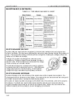
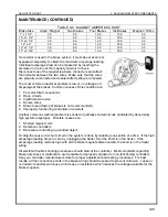
For E-Z Lube® axles using the new nut retainer
:
1. After placing the hub, bearings, washers and spindle nut back on the axle spindle in reverse order
as detailed in the previous section on hub removal, rotate the hub assembly slowly while
tightening the spindle nut to approximately 50 ft-lb (68 N-m), (12” (30 cm) wrench or pliers with full
hand force.)
2. Then loosen the spindle nut to remove the torque. DO NOT rotate the hub.
3. Finger-tighten the spindle nut until just snug; align the retainer to the machined flat on the spindle
and press the retainer onto the nut. The retainer should snap into place. Once in place, the
retainer / nut assembly should be free to
move slightly.
4. If the nut is too tight, remove the retainer
and back the nut off approximately one
twelfth of a turn and reinstall the retainer.
The nut should now be free to move
slightly.
5. Reinstall grease cap.
Typical E-Z Lube® After Spring 2002
Summary of Contents for 3522A
Page 1: ...OPERATOR S MAINTENANCE MANUAL B33 01 0093 Rev 4 May 2013...
Page 76: ...HAULOTTE GROUP 6 DECAL REPLACEMENT 76 DECAL KIT ANSI...
Page 78: ...HAULOTTE GROUP 6 DECAL REPLACEMENT 78 IDENTIFICATION PLATES OPTIONAL EQUIPMENT ANSI...
Page 84: ...HAULOTTE GROUP 6 DECAL REPLACEMENT 84 DECAL KIT CE...
Page 86: ...HAULOTTE GROUP 6 DECAL REPLACEMENT 86 IDENTIFICATION PLATES OPTIONAL EQUIPMENT CE...
Page 88: ...HAULOTTE GROUP 6 DECAL REPLACEMENT 88 DECAL KIT AU...
Page 90: ...HAULOTTE GROUP 6 DECAL REPLACEMENT 90 IDENTIFICATION PLATES OPTIONAL EQUIPMENT AU...
Page 92: ...HAULOTTE GROUP 6 DECAL REPLACEMENT 92...
Page 106: ...HAULOTTE GROUP 8 MATERIAL SAFETY 106 MATERIAL SAFETY DATA SHEET POWERFLOW AW HVI HYDRAULIC OIL...


