


30
SYSTEM CONFIGURATION
System Configuration
Step 2.
Select one of the two options shown
based on the way you wish to have the system
settings entered:
• In most cases, you will want to use the
Automatic mode, which calibrates the system
for speaker presence, speaker “size”, speaker
crossover, channel output level, speaker-to-
listener delay time and room equalization. To
choose this mode simply press the
Set Button
F
, as the cursor is already pointing to
AUTOMATIC E Q DESIGN
when the
menu appears on the screen.
Then press the
Set Button
F
again when the
AUTOMATIC EZSET/EQ
menu appears,
to continue to Step 3.
• If you wish to enter the speaker crossover
frequencies yourself, but want to have the
EzSet/EQ system test for and calibrate all the
other functions listed above, press the
¤
Navigation Button
E
to point the cursor
at
EZSET/EQ SETUP
and then press the
Set Button
F
. Once the
MANUAL
SETUP
menu (Fig. 18) appears, follow the
instructions on page 32 to enter your desired
settings for the Crossover Frequencies, and
then return to the
EZSET/EQ MAIN
menu. Press the
¤
Navigation Button
E
again so that the cursor is pointing to
MANUAL E Q DESIGN
and then press the
Set Button
F
. When the interim message
screen appears to remind you to set the
crossovers, make sure that the cursor is point-
ing to
CONTINUE
and press the
Set
Button
F
again since you have already set
the crossovers.
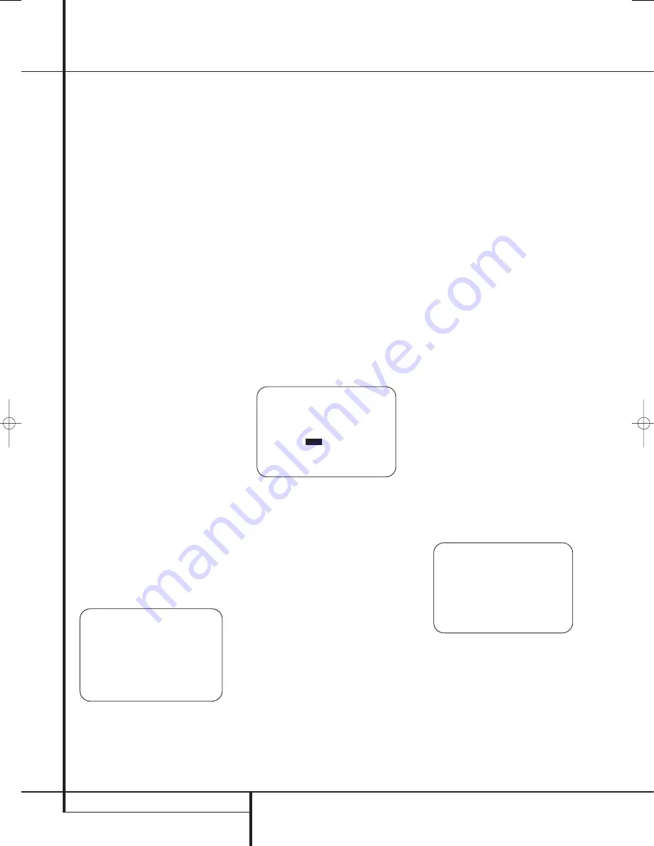
Step 3.
The
FAR FIELD MEASURE
screen (Figure 17b) will appear with instructions
to place the microphone, if you have not already
done so. This screen is also the place to set the
master volume level. As noted on the screen, use
the
Volume Control
ı
to adjust the vol-
ume level to –35dB, as shown on the line that
appears at the bottom of the menu when the
volume is adjusted. Press the
Set Button
F
when the volume is set to the proper level.
Figure 17b
Step 4.
The final menu screen before the
EzSet/EQ process starts is a warning screen
(Figure 17c) that serves as a reminder to keep
the room as quiet as possible while the system is
in use. Extraneous noise of any kind may
adversely affect the accuracy of the system’s
results. Do not talk while the test tones are
circulating, and if possible, turn off any ventila-
tion systems if the noise form the air flow is loud
enough for you to hear. Should an outside noise
such as a phone ringing occur during the test
process, we recommend that you rerun EzSet/EQ.
If you do not wish to start the test process at this
time, press the
⁄
/
¤
Navigation Button
E
to return to either the EzSet/EQ menu or the
Master Menu, and press the
Set Button
F
. To
begin the EzSet/EQ Near Field measurements,
press the
‹
/
›
Navigation Button
E
so that
O N
is highlighted in reverse video, and press the
Set Button
F
.
NOTE:
Once the EzSet/EQ process starts, the
volume control and Standby/Off switches are
temporarily disabled while the tests are in
progress. Do not adjust the volume or turn the
unit off until you see the on-screen message
change to indicate that EzSet/EQ is finished.
Figure 17c
Step 5.
At this point you will begin to hear a
series of test tones circulate among all the
speakers in your system. While this is happening,
the AVR is reading the signal to determine which
speaker positions are active, what type of
speaker is present at each active position, what
the distance is from the listening position to each
speaker, and to begin to build a profile of the
impact of the room’s acoustics on the quality of
audio reproduction. When the test is completed
you will hear the tones stop, and the system will
pause fors long as a minute while the processor
makes its calculations. Do not be alarmed if the
“WARNING” message remains on the screen
after tones stop until a results message is
displayed as shown in Step 6 or 7, below.
NOTE:
While these tests detect whether a
speaker is connected to a particular output, they
cannot determine whether the speaker is in the
correct position. (For example, it can tell whether
a speaker is connected to the Surround Right
output, but it cannot tell whether the speaker is
on the right or left side of your listening room.)
For that reason, we strongly recommend that you
try to listen as the tone circulates, matching the
name shown for each channel to the location of
the speaker. If a tone is heard from a speaker
position that does not match the on-screen
message, make a note of the incorrect speaker
connections. When the test process stops you will
see a message indicating the they Far Field
measurements are complete, but since there is a
connection error press the
¤
Navigation
Button
E
so that the on-screen cursor in
Fig. 7 is pointing to
RETURN T O MASTER
MENU
and press the
Set Button
F
. At this
point, exit all menus and turn the receiver off.
Check all speaker wire connections and then
rerun EzSet/EQ.
Step 6.
When the Far Field tests are complete a
message screen will appear to confirm if the pro-
cedure was successful or not. In most cases there
will not be any problems and you will see the
message shown in Figure 17d on your screen. If
the speaker positions shown match the actual
speaker layout in your system, press the
Set
Button
F
to complete EzSet/EQ by performing
the Near Field Measurements. Continue the
EzSet/EQ process by pressing the
Set Button
F
to take the Near Field measurements from
the front left, center and right speakers. By taking
this separate set of measurements, the AVR is
able to complete its view of the room’s sonic
signature and apply equalization as needed to
correct spikes and dips in the system’s response.
Continue these instructions with Step 8.
Figure 17d
* F A R F I E L D C O M P L E T E *
E Q s u c c e s s f u l
S p e a k e r c o n f i g d e t e c t e d
F L : Y E S S B R : Y E S
C E N : Y E S S B L : Y E S
F R : Y E S S L : Y E S
S R : Y E S S U B : Y E S
D O N E A R F I E L D
B A C K T O M A S T E R M E N U
→
W A R N I N G ! !
D u r i n g m e a s u r e m e n t
p l e a s e m a i n t a i n s i l e n c e
w h i l e s e v e r a l s o u n d
b u r s t s a r e h e a r d .
S T A R T :
O F F
O N
B A C K T O E Z S E T / E Q M O D E
B A C K T O M A S T E R M E N U
→
* F A R F I E L D M E A S U R E *
P l a c e m i c a t e a r l e v e l
n e a r t h e l i s t e n i n g
p o s i t i o n a t l e a s t 3 f t /
1 m f r o m a n y h a r d
s u r f a c e .
S e t v o l u m e t o - 3 5 d B
C O N T I N U E
B A C K T O E Z S E T / E Q M A I N
B A C K T O M A S T E R M E N U
V O L U M E : - 3 5 d B
→
29851_AVR645_ENG 30/10/06 9:46 Side 30


