Harman Kardon AVR 645 Owner'S Manual Download Page 27

SYSTEM CONFIGURATION

27

ENGLISH

System Configuration

Surround Setup

The next step for that input is to set the surround
mode you wish to use with that input. Since sur-
round modes are a matter of personal taste, feel
free to select any mode you wish – you may
change it later. The Surround Mode chart on page
38 may help you select the mode best suited to
the input source selected. For example you may
select Dolby Pro Logic II or Logic 7 for most
analog inputs and Dolby Digital for inputs con-
nected to digital sources. In the case of inputs
such as a CD Player, Tape Deck or Tuner, you may
wish to set the mode to Stereo, if that is your
preferred listening mode for standard stereo
sources, where it is unlikely that surround encod-
ed material will be used. Alternatively, the 5
Channel Stereo or Logic 7 Music mode may also
be a good choice for stereo-only source material.

It is easiest to complete the surround setup using
the full-OSD on-screen menus. From the

MASTER

menu (Figure 7), press the 

/

¤

buttons 

E

F

until the 

cursor is next to the

SURROUND SELECT

menu. Press the

Set

Button

F

Q

so that the 

SURROUND

SELECT

menu (Figure 13) is on the screen.
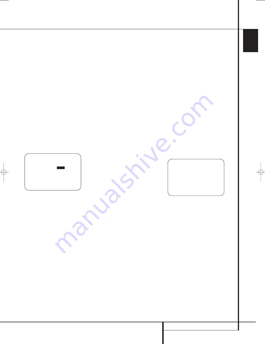
Figure 13

The first line on the menu allows you to select
the input for which the specific surround settings
will be applied. Press the 

/

Navigation

Buttons

E

F

to select the input source to

be configured.

The 

AUDIO IN-PORT

and 

AUDIO I N

lines are for display only and may not be
changed through the 

SURROUND SETUP

menu. The 

AUDIO IN-PORT

displays the

physical connection source for the current active
input, and the 

AUDIO I N

line shows the

signal type present. Note that an 

UNLOCK

message in the 

AUDIO I N

line indicates that

a digital physical input source has been selected,
but that no data stream is present.

When the input selection has been made, press
the 

/

¤

Navigation Button

E

F

to move

to the next configuration line.

The 

ADC SAMPLING

line is where you

determine whether the unit’s upsampling feature
is turned on or off. The default setting of 48kHz
puts the feature in a bypass, or “off,” mode and
will pass digital audio data through the DSP at
its native sample rate. To process incoming
44.1kHz signals at a higher resolution,
upsampled 96kHz sample rate, press the 

/

Navigation Buttons

E

F

once so that

96kHz is highlighted.

When the desired setting has been made, or if no
adjustment is required at this line, press the

/

¤

Navigation Button

E

F

to move to

the next configuration line.

The 

SURR MODE

and 

SELECT

lines are

related, as they guide you to the choice of the
surround mode that will be activated whenever
the input being configured is selected.

At the 

SURR MODE

line, press the 

/

Navigation Buttons

E

F

to select the sur-

round mode group (such as Dolby modes, DTS
modes, Logic 7 modes, and DSP or Stereo modes)
that is applicable to the input source. After mak-
ing a selection, press the 

/

¤

Navigation

Button

E

F

to move to the 

SELECT

line.

At the 

SELECT

line, you are able to choose

the specific mode to be used from within the
major surround mode group. The choice of modes
is governed by the input type (as some modes
such as Dolby Digital or DTS-ES are not available
for analog sources), as well as by the speaker
configuration, since some modes are only
available when a full 7.1 speaker complement is
present. The full list of available modes is
detailed in the surround mode chart on page 38.
In addition, you may also use the settings in the

SURROUND CONFIG

menus to delete

modes you do not normally use from the
available choices.

When both a surround mode group and a
specific surround mode have been selected, press
the 

/

¤

Navigation Button

E

F

to move

to the next configuration line.

The 

DEFAULT SURR

mode line is where you

choose the mode that is activated when a digital
source is selected. The factory default setting of

LAST

will activate the last-used mode for any

digital source. If you prefer to always have a digi-
tal source switch to the specific mode encoded
by digital data flags in the incoming audio data
stream, press the 

/

Navigation Buttons

E

F

so that 

ORIGINAL

appears.

Before proceeding to the 

SURROUND

CONFIG

line, it is worth noting that the set-

tings in the submenus attached to that line may
require a considerable amount of time to com-
plete. Although they are useful in that they allow
you to customize the list of surround modes that
appear in normal use of the AVR, you may wish
to bypass those settings at this time so that you
may complete the configuration process. You may
return to this menu line at a later time, once you
have had a chance to listen to the various sur-
round modes and determine which you want to
“keep” and which you do not want to use. The
settings in this line are not primary controls and
do not impact the way the AVR “sounds.”

To proceed to the 

SURROUND CONFIG

line, press the 

/

¤

Navigation Button

E

F

to move to that line; otherwise, press it

again to move to the 

DOLBY SURR

SETUP

line and skip to the instructions for

that setting.

The 

SURROUND CONFIG

line is your

gateway to a broad range of surround mode
configurations. To continue, press the

Set

Button

F

Q

to go to the main

SURROUND CONFIG

menu (Figure 14).

Figure 14

The 

LOGIC 7 GLOBAL

line is the only item

on this menu page that is menu-specific, and it
allows you to select whether or not Logic 7 will
be the default surround mode for any incoming
audio signal. The default setting is 

OFF

, which

chooses the native mode. Press the 

/

Navigation Buttons

E

F

so that 

O N

appears, to activate the global Logic 7 setting for
this input.

The remaining five items in this menu are global
settings that take you to a submenu listing the
individual surround modes available within the
selected mode group. To select a surround mode
list, press the 

/

¤

Navigation Button

E

F

until the on-screen cursor is pointing to

the desired mode, and then press the

Set

Button

F

Q

. Within each menu, press the

/

¤

Navigation Button

E

F

to move the

cursor up and down through the list, and then
press the 

/

Navigation Buttons

E

F

to

turn the mode “ON” or “OFF.”

* *   S U R R O U N D   C O N F I G   * *

L O G I C   7   G L O B A L : O F F
D O L B Y   M U L T I   C O N F I G
D O L B Y   2 . 0   C O N F I G
D T S   C O N F I G
P C M   4 4 . 1 / 4 8 k H z   C O N F I G
P C M   9 6 k   C O N F I G

B A C K   T O   S U R R O U N D   C O N F I G


➔  

➔  

* *   S U R R O U N D   S E T U P   * *  
S O U R C E :     V I D E O   1
A U D I O   I N   P O R T :   A N A L O G
A U D I O   I N :   P C M   4 4 . 1 k H z
A D C   S A M P L I N G :  

4 8 K

  9 6 K

S U R R   M O D E :   L O G I C   7
S U R R   S E L E C T :   M U S I C   5 . 1
D E F A U L T   S U R R :   L A S T
S U R R O U N D   C O N F I G
D O L B Y   S U R R   S E T U P
B A C K   T O   M A S T E R   M E N U

➔  

➔  

29851_AVR645_ENG  30/10/06  9:46  Side 27

Summary of Contents for AVR 645

Page 1: ...ENGLISH AVR 645 AVR 645 Audio VideoReceiver OWNER S MANUAL...

Page 2: ...ypographical Conventions In order to help you use this manual with the remote control front panel controls and rear panel connections certain conventions have been used EXAMPLE bold type indicates a s...

Page 3: ...s for use with portable recorders a Harman Kardon exclusive Two video recording outputs preamp out and a color coded eight channel input make the AVR virtually future proof with everything needed to a...

Page 4: ...serviceable components inside this product Opening the cabinet may present a shock hazard and any modification to the product will void your guarantee If water or any metal object such as a paper cli...

Page 5: ...e For example press this button to select Dolby modes and then press the Surround Mode Selector 9 to choose from the various mode options 6 Speaker Selector Press this button to begin the process of c...

Page 6: ...he Digital Coax 4 Jack to an output Video 4 Input Output Jacks These audio video jacks may be used for temporary connection to video games or portable audio video products such as camcorders and porta...

Page 7: ...rround Right Gray Surround Back Left Brown Surround Back Right Tan Subwoofer LFE Purple Digital Audio Orange Composite Video Yellow Component Video Y Green Component Video Pr Red Component Video Pb Bl...

Page 8: ...sten to audio from the computer through the AVR 645 This connection is also used to connect a compatible computer to the AVR for firmware upgrades when available See page 43 for more information on pl...

Page 9: ...es be made by a trained and qualified technician This jack may also link to a compatible computer to upgrade the software and operating system of the AVR 645 when appropriate upgrades are available Fa...

Page 10: ...tal Mode Selector Logic 7 Mode Select Button Transport Controls Light Button Skip Up Down Buttons Stereo Mode Select Button DTS Neo 6 Mode Select Macro Buttons Disc Skip Button Preset Up Down Clear Bu...

Page 11: ...ve for control of the other device such as a DVD player or set top box until you manually return control to the AVR by pressing the AVR Selector 5 follow the instructions on page 40 5 AVR Selector Pre...

Page 12: ...II modes Dolby 3 Stereo or Dolby Digital Note that the Dolby Digital mode is only available with a digital input selected and the other modes only as long as a Dolby Digital source is not playing exc...

Page 13: ...tton to begin the process of configuring the AVR s Bass Management System for use with the type of speakers used in your system Once the button has been pressed use the buttons E to select the channel...

Page 14: ...optional infrared sensor that is connected to the AVR s Multi IR input jack We strongly recommend that the ZR 10 remote be used for the initial configuration and setup process for the AVR 645 A Power...

Page 15: ...e button simply press the proper Numeric Keys G to select a station See page 51 for more information on the tuner N Memory Button Press this button to enter a radio station into the AVR s preset memor...

Page 16: ...tistrand copper with an area greater than 2 mm2 Cable with an area of 1 5 mm2 may be used for short runs of less than 4 m We do not recom mend that you use cables with an area less than 1 mm2 due to t...

Page 17: ...compatible with Based on the lowest level of HDMI among your sources the connections to the AVR should be made as follows HDMI 1 0 sources carry digital video and mul tichannel or 2 channel PCM audio...

Page 18: ...lowing Scart to Cinch adapters or cables are needed Units for playback such as satellite receivers camcorders DVD or LD players need an adapter from Scart to 3 RCA plugs see fig 1 normal video devices...

Page 19: ...with a SCART cable specific control signals apart from Audio Video signals will be fed to the TV These specific signals are With all video sources the signal for automatic input selection that switche...

Page 20: ...mote location speakers in the same room as the AVR and connect the Multiroom Output jacks on the rear panel of the AVR to the audio input of the remote room amplifier Use the appropriate speaker wire...

Page 21: ...Jack The AVR draws significantly more current than other household devices such as computers that use removable power cords For that reason it is important that only the cord supplied with the unit o...

Page 22: ...One method of finding the optimal location for a subwoofer is to begin by placing it in the front of the room about 15cm from a wall or near the front corner of the room Another method is to temporar...

Page 23: ...y modes Semi OSD and Full OSD When making con figuration adjustments it is recommended that the Full OSD mode be used This will place a complete status report or option listing on the screen making it...

Page 24: ...entered up to a maximum of fourteen characters Press the Set Button F to enter the input name into the system memory and to proceed with the configuration process The audio input defaults for all sour...

Page 25: ...V SYNC DELAY line and then press the Navigation Button EF until the desired amount of delay is applied so that the on screen video matches the audio When all configuration adjustments on this menu sc...

Page 26: ...o HDMI when an HDMI signal is detected If a high definition input source is not HDCP content protected it may be output through the compo nent jacks otherwise it will be sent only to the HDMI outputs...

Page 27: ...uration since some modes are only available when a full 7 1 speaker complement is present The full list of available modes is detailed in the surround mode chart on page 38 In addition you may also us...

Page 28: ...lete expla nation of these modes is found on Page 38 The Dolby Digital EX mode is only available when the system is set for 6 1 7 1 operation by config uring the Surround Back speakers to Small or Lar...

Page 29: ...he Texas Instruments DA 610 digital signal proces sor EzSet EQ eliminates the need for manual adjustment of speaker size crossover delay and output level settings while it adds the power of a multi ba...

Page 30: ...the speakers in your system While this is happening the AVR is reading the signal to determine which speaker positions are active what type of speaker is present at each active position what the dist...

Page 31: ...ontain an option to return to the NEAR FIELD EQ SELECT menu Figure 17g as well as the ability to return to the MASTER MENU If you are ready to proceed with the test make certain that the microphone is...

Page 32: ...OFF is shown you are able to make any required adjustments that are available on that menu However you may change the setting to ON at any time to recall the settings established when EzSet EQ was las...

Page 33: ...ont left right when LARGE is chosen no derived sound will be sent to the sub woofer output although in all cases the special low frequency effects LFE signals available on 5 1 or 6 1 digital programs...

Page 34: ...he setting for a 10 inch 250mm driver activates a 30Hz subwoofer high pass filter The setting for a 12 inch 305mm driver activates a 20Hz subwoofer high pass filter The setting for a 15 inch 380mm dri...

Page 35: ...will unlock the menu to allow changes When the delay time for all speaker positions has been set you may return to the master menu by pressing the Navigation Button EF until the cursor is pointing to...

Page 36: ...then pressed to select OFF in the highlighted video The final option for tone adjustment using the menu system is to not use the internal test tone at all To do this simply use the Navigation Button...

Page 37: ...he channel output levels for any input without changing the settings previously established for another When all changes to the Channel Output levels and the associated level trim settings have been m...

Page 38: ...that are recorded with matrix surround or even with normal stereo mode creating separate rear left and rear right signals in any case The Pro Logic II mode creates compelling five channel surround sou...

Page 39: ...Speaker Dolby Virtual Speaker technology uses a next generation advanced algorithm to reproduce the Reference dynamics and surround sound effects of a precisely placed 5 1 channel speaker system using...

Page 40: ...t time that input was used The front panel Video 4 Inputs Optical Digital 4 Input or the Coaxial Digital 4 Input may be used to connect a device such as a video game or camcorder to your home entertai...

Page 41: ...ic with music surround mode with any DTS NEO 6 mode or with Harman Kardon s exclusive Logic 7 Movie Mode to create a full range 5 1 channel or with Logic 7 and DTS NEO 6 even 7 1 channel surround sign...

Page 42: ...speaker channels available in your system once the AVR locks to the digital signal you may select any surround mode or post processing option that is available based on the incoming data stream s pos...

Page 43: ...ital 5 1 and DTS 5 1 programs A 2 tells you that separate front left and right signals are available but there is no discrete center channel signal This will be displayed for Dolby Digital bit streams...

Page 44: ...s playing the letters in these indicators will light in response to the specific signal being received It is important to note that although Dolby Digital for example is referred to as a 5 1 system no...

Page 45: ...seated The AVR s front panel controls may also be used to access a limited number of iPod functions Press the AM FM to play or pause the current track The Tuning Selector may be used to search in rev...

Page 46: ...rease the level of the rears when you find it to be too low with specific surround modes If you wish to reset all the levels to their original factory default of 0dB offset press the Buttons E so that...

Page 47: ...emind you that the unit is turned on If you wish to make other adjustments in the menu press the Buttons E until the on screen cursor is next to the desired setting or the BACK TO MASTER MENU line and...

Page 48: ...ton F If you have no other adjustments to make press the OSD Button L to exit the menu system Full OSD Time Out Adjustment The FULL OSD menu system is used to simplify the setup and adjustment of the...

Page 49: ...www harmankardon com or contact our customer service department Multiroom Setup Once the audio and IR link connections have been made the AVR needs to be configured for multiroom operation using the s...

Page 50: ...ystem on or off even when the AVR is in the Standby mode in the main listening room IMPORTANT NOTE When an A BUS module is connected the AVR s Multiroom system must be turned on before the A BUS modul...

Page 51: ...2 Within five seconds press the Numeric Keys H corresponding to the location where you wish to store this station s frequency Once entered the preset number will appear in the Main Information Display...

Page 52: ...a specific Program Type PTY by following these steps 1 Press the RDS button until the current PTY is shown in the Main Information Display 2 While the PTY is shown press the Preset Up Down button or...

Page 53: ...he remote s library at all you may still use the AVR remote to program most infrared controlled products by learning the commands from the product s original remote into the AVR remote The instruction...

Page 54: ...member if the device turns off skip to Step 9 When all the codes for the device being programmed have been tried the instruction shown in Figure 34 will appear This means that the codes for the produc...

Page 55: ...lay when the button that has just had a new code learned is pressed press the Navigation Buttons E so that the display shown in Figure 42 appears in the LCD display Press the Set Button F to open the...

Page 56: ...es into the AVR remote using the process outlined on page 54 To begin the process start by selecting the brand of device as shown in Figure 29 Press the Navigation Buttons E until the brand name of th...

Page 57: ...wer On followed by the Cable Box On followed by the selection of the Logic 7 mode To do that press the buttons in this order Power On 3 VID 2 TV 4 Power On 3 VID 3 Cable 4 Power On 3 AVR 5 Logic 7 O A...

Page 58: ...To have the AVR s volume commands used when the TV device is selected follow these steps 1 Press and hold the Program Button for about three seconds while the message shown in Figure 25 appears in the...

Page 59: ...ICE IN USE on the left side of the bottom line and the PUNCH THROUGH device In the example used the display to return the remote to default settings will appear as shown in Figure 68 Figure 68 Transpo...

Page 60: ...on generates 7 After you enter the first letter of the new device name there are three options for entering the next character a To enter a letter that requires a different numeric key to be pressed s...

Page 61: ...ic key you must first press the Navigation Buttons E to move the blinking cursor block to the next position Then press the Numeric Key H as required to enter the desired letter This is the way you wou...

Page 62: ...to indicate that the setting has been accepted by the remote s memory 5 The remote s backlighting will now turn on whenever a button is pressed To revert to the original setting follow the four steps...

Page 63: ...ction when Main No AC Power Make certain AC power cord is plugged Power Switch 1 is pushed into a live outlet Check to see if outlet is switch controlled Display lights but no sound Intermittent input...

Page 64: ...NALOG DVD COAX 1 AUTO COMPONENT 3 ANALOG HDMI 1 HDMI 1 HDMI 1 DSP DOWNMIX HDMI 2 HDMI 2 HDMI 2 DSP DOWNMIX Tuner ANALOG AUTO COMPONENT 1 ANALOG CD ANALOG AUTO COMPONENT 3 ANALOG Tape ANALOG AUTO COMPO...

Page 65: ...er 12 0 Feet Front Right 12 0 Feet Surround Right 12 0 Feet Surround Back Right 12 0 Feet Surround Back Left 12 0 Feet Surround Left 12 0 Feet Subwoofers 12 0 Feet Worksheet D System Defaults and Sett...

Page 66: ...2 CD Tape Tuner The Bridge USB 6 8 Ch Direct Input Title Surround Mode Audio In Port Audio Auto Poll Video In Port Component Video Input Video Processing A V Sync Delay Record Output Auto Poll Input...

Page 67: ...Version 1 1 General Power Requirement AC 220 240V 50Hz Power Consumption 120W idle 1180W maximum 7 channels driven Dimensions Max Width 440mm Height 165mm Depth 435mm Weight 19 9 kg Depth measurement...

Page 68: ...250 Crossways Park Drive Woodbury New York 11797 www harmankardon com Harman Consumer Group Inc 2 route de Tours 72500 Ch teau du Loir France 2006 Harman Kardon Incorporated Part No ZKD3001HA00 R...

Reviews: