background image

-CS    -15

P.FOOT

T.CUT

MENU

FORWARD

ENT.

P.FOOT

T.CUT

MENU

FORWARD

ENT.

P.FOOT

T.CUT

MENU

FORWARD

ENT.

P.FOOT

T.CUT

MENU

FORWARD

ENT.

P.FOOT

T.CUT

MENU

FORWARD

ENT.

P.FOOT

T.CUT

MENU

FORWARD

ENT.

P.FOOT

T.CUT

MENU

FORWARD

ENT.

P.FOOT

T.CUT

MENU

FORWARD

ENT.

P.FOOT

T.CUT

MENU

FORWARD

ENT.

FORWARD

P.FOOT

T.CUT

MENU

ENT.

  ID:10 Nd: 4

       BIRD

G

LET'S TURN ON THE MACHINE

3_6   D424

3-6

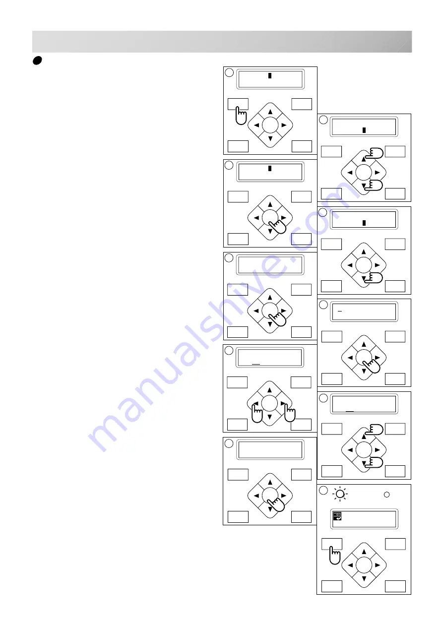
Calendar and clock setting

If you set up the calendar and clock, the ma-
chine will advise when oiling and other mainte-
nance is scheduled to occur.

1. Press the "MENU" button until the display

shows [MENU] while the machine is
stopped.

2. Select "Other" by pressing the up and down

"Arrow" buttons.

3. Press the "ENT.” button.

4. Select "Clock" by pressing the down "Ar-

row" button.

5. Press the "ENT.” button.

The display will show the month, date, year, day
and time.

6. Press the "ENT.” button.

A cursor ( _ ) will appear at the bottom of the
month. You can then set the number.

7. Move the cursor to the next item you wish

to change by using the “right” and “left”
Arrow buttons.

8. Change the numbers by using the “up” and

“down” Arrow buttons.

9. Press the "ENT.” button.

If you wish to change other item of calendar and
clock, Please continue 7. and 8.

10.Finally, Press "MENU" button until the

green lamp is showing on the control box.

If a green lamp is showing, you are in “Drive”
mode.

[MENU]  Pattern
        Needle

1

[MENU]  Letter
        Other

2

 1.23.2003.THU
10:09:56

 1.23.2003.THU
10:09:56

 1.23.2003.THU
10:10:56

 1.23.2003.THU
10:10:56

6

 1.23.2003.THU
10:09:56

7

8

[OTHER] Setup
        Clock

3

[OTHER] Setup
        Clock

4

5

9

10

Summary of Contents for HCS

Page 1: ...INSTRUCTION BOOK COMPACT ELECTRONIC EMBROIDERY MACHINE HCS CSK101 2...

Page 2: ......

Page 3: ...ogram letters 5 10 SETTING AUTOMATIC COLOR CHANGE 5 15 SEWING WITH TUBULAR FRAMES Installing and removing the frame base 6 1 How to hoop 6 2 Putting the hoop in the machine 6 3 Starting to sew 6 4 CAP...

Page 4: ...or mechanical adjust ment 4 Never operate the appliance with any air openings blocked Keep ventilation openings of the sewing machine and foot controller free from the accumulation of lint dust and lo...

Page 5: ...e moving heads while the machine is running Laser beam Class 1 Do not stare into the beam ES HMF 5113 0 WARNING Shut the cover when starting the machine Do not put hands in while the machine is runnin...

Page 6: ...foam right and left 5 Take out the styrene foam lower front lower right and lower left Be careful not fall down the machine tilt the machine slightly when taking out the styrene form lower right and...

Page 7: ...manual Parts list CD ROM HAPPY Link Software Instruction manual Embroidery sample Embroidery frame Round Embroidery frame Square Thread stand Thread guide bracket Carriage Thread stand felt 13 pcs USB...

Page 8: ...15 360 11 Needle DB X K5 10 pcs 12 Oiler 13 Sewing machine oil 14 CD ROM Happy Link 15 CD ROM Instruction manual Parts list 16 Instruction book How to open the CD ROM 17 USB cable 18 Power line cord a...

Page 9: ...t is nec essary when packing 5 Put the carriage and carriage arm together with screw M4 X 8 2 pcs 2 pins in the upper carriage arm will fit into holes on the lower carriage 6 Raise slowly the control...

Page 10: ...table when the machine is running If you have a problem Please use a stronger table for the machine 2_4 D607 2 4 SETTING UP THE MACHINE 350 mm 350 mm 720 mm 2 Please sit the machine level on the table...

Page 11: ...right side drawing 5 Please do not sit the machine near any kind of other electric equipment Examples Microwave or electric tool Has possible to wrong movement of the machine 6 Please keep away from...

Page 12: ...roperly grounded Do not modify the plug provided with the product if it will not fit the outlet have a proper outlet installed by a qualified electrician This product is for use on a nominal 120 V cir...

Page 13: ...roller 11 Minor thread tension 12 Thread guide support 13 Thread guide 14 Upper rectifier 15 Thread stand pin 16 Thread stand felt 17 Thread stand 18 Needle bar selection knob 19 Control box 20 Serial...

Page 14: ...tton 41 Needle change button 42 Speed control button 43 Start button 44 Stop button 45 Contrast control dial 46 Memory card eject button 47 Memory card slot 48 USB memory port BOBBIN WINDING 49 Upper...

Page 15: ...en the machine is stopped Press MENU button until display shows MENU 2 Select the design name you wish to sew by use of the up and down arrow buttons 3 When you press the ENTER button the machine will...

Page 16: ...h c a m e h T e h t d e h s i n i f s a h t i e s u a c e b n g i s e d n g i s e d t x e n w e s o t h s i w u o y f I y r e d i o r b m e e c a l p e r e s a e l P e m a r f p o t S e g n a h C u o...

Page 17: ...ion then remove plug from outlet DANGER To reduce the risk of electric shock Never leave the machine unattended when plugged in Always unplug this machine from the electric outlet immediately after us...

Page 18: ...f carriage for creating the coordinates of frame posi tion The following functions is canceled by selecting Non Registered Frame Restore the position at the time of power failure 9 2 Autostop function...

Page 19: ...18 LET S TURN ON THE MACHINE If the display is not clear Please adjust the contrast of the LCD display by turning the small dial on the right side of the control box 3_5c H701 3 5c Contrast control d...

Page 20: ...3 Press the ENT button 4 Select Clock by pressing the down Ar row button 5 Press the ENT button The display will show the month date year day and time 6 Press the ENT button A cursor _ will appear at...

Page 21: ...o not remove memory media when this icon is displayed If you remove the memory media when this Icon is displayed it is possible to corrupt the design data in the machine memory and on the memory media...

Page 22: ...sly Push the stop button again to stop it L Speed control button Press the button to increase the machine sewing speed and the button to lower the machine speed The sewing speed is shown on the displa...

Page 23: ...ORWARD MENU P FOOT T CUT ENT START STOP MENU Needle Auto needle change 5 15 MENU Read Memory media 5 6 MENU Convert Convert 9 5 MENU F Posi Frame position 9 6 MENU Create Create 5 1 MENU Pattern Patte...

Page 24: ...before removing the needle 1 Loosen the needle clamp screw slightly with the screw driver 2 Remove the needle 3 Insert a new needle into the needle clamp with push it up as far as it will go keeping...

Page 25: ...7 0 6 0 5 0 0 1 0 8 0 3 1 0 0 1 0 3 1 0 0 1 2 1 0 8 3 1 5 8 0 4 6 3 0 7 0 6 0 0 1 0 8 0 5 1 0 3 1 4 1 0 9 5 1 5 9 6 1 0 0 1 6 3 0 3 0 6 0 5 0 8 0 6 0 6 1 0 5 1 7 1 5 0 1 8 1 0 1 1 0 3 4 2 0 5 0 4 0 6...

Page 26: ...iful embroidery Select backing type Choose the thickness and number of sheets by the type of material and embroidery condition Generally you should consider the following items Embroidery stitch quali...

Page 27: ...w to start the winder The lever stops the winder automatically after the winding is complete 1 2 3 4 5 Increase Decrease Tension When adjusting bobbin winder tension Ensure thread winds evenly on bobb...

Page 28: ...thread on top leading from left to right 2 Insert bobbin in case and draw thread up into slot in case 3 Draw thread under tension spring A and wind into guide coil B The bobbin should turn clockwise i...

Page 29: ...read Pass upper threads in order according to the figure 1 Thread stand Set thread cone on the stand Small cones can also be used as shown 2 Thread guide Thread through the thread guide above each thr...

Page 30: ...clock wise 9 Upper thread guide 10 Lower thread guide 11 Lower rectifier 12 Thread guide plate upper 13 Thread adjusting spring 14 Thread guide plate upper 15 Take up lever 16 Thread guide plate uppe...

Page 31: ...down Arrow buttons 3 Press ENT button The indicator will dis play a machine setting 4 Press up and down Arrow button until it comes to the setting you wish to change 5 Press ENT button to display a cu...

Page 32: ...t c n u f m i r t e v a h t o n s e o d a t a d f I m i r t h c t i t S 3 1 r e p e e w s s e Y o N a t a d n r e t t a p g n i d a e r n e h w s e h c t i t s t r o h s y l e m e r t x e s e t a n i...

Page 33: ...ng 18 Trace type Select type of design trace You can compare the design size and design position to the embroidery frame before you start sewing The embroidery frame moves around the actual design siz...

Page 34: ...nctions by using the Happy Link software Please refer to the Happy Link software manual for instructions 5_4 FA27 USB connection based on the USB 1 1 2 0 Connect by USB cable between USB port of the m...

Page 35: ...art media card memory stick SD card which are inserted into a PCMCIA card adaptor If you insert a LAN card or PCMCIA card other than noted above it is possible the machine will break down Handling not...

Page 36: ...o the USB memory port of the machine right side of controller 2 Read embroidery design data according to following Memory card reading in the next section To remove a USB memory 1 Please check that th...

Page 37: ...MENU ENT FORWARD P FOOT T CUT MENU ENT FORWARD P FOOT T CUT MENU ENT FORWARD P FOOT T CUT MENU ENT ID 14 Nd 6 FANTASIA G MENU Pattern Needle MENU Read Convert 2 RD ANIMAL FANTASIA RD ANIMAL FANTASIA...

Page 38: ...ber of a pattern you can select 5 Press the Up and Down Arrow button to choose the embroidery pattern 6 Press the ENT button The display will show OK or Cancel 7 Press the ENT button Make your selecti...

Page 39: ...dure 6 Push the Down arrow button and ENT button to cancel deleting of the design Return to the drive mode 9 Finally Press MENU button until the green lamp on the control box glows When a green light...

Page 40: ...OK 7 Press the ENT button You will then return to drive mode Push the Up arrow button and then push the ENT button to cancel Returns to Drive mode after cancelation of design delete Nd 14 HAPPY FORWAR...

Page 41: ...FOOT T CUT MENU ENT WRITE Card USB 1 Press the MENU button until MENU is showing when machine is stopped 2 Press the Up or Down arrow button until the cursor points to Pattern 3 Press the ENT button...

Page 42: ...to 12 is repeated and a menu button will be pushed if a design name is changed Or of letter pallet decision is chosen 14 Press the ENT button After displaying it as gWriting data g the beginning is en...

Page 43: ...rrow button until the cursor points to Letter 3 Press the ENT button when showing LETTER Letter selection Char To select letters 15 letters maximum 4 Press the Up or Down arrow button until the cursor...

Page 44: ...10 Repeat the procedure 6 thorough 9 above to select additional letters If you wish to insert a Space it will not be recog nized as a letter 11 Press the MENU button when you are finished with the le...

Page 45: ...rrow button 17 Press the ENT button when showing SIZE 18 Press the Up or Down arrow button to select the size of the letter Large 15 mm height Middle 10 mm height Small 4 mm height 19 Press the ENT bu...

Page 46: ...letter settings 26 Select Mode by pressing the Down arrow button 27 Press the ENT button To select Refer or On Select Refer 28 By pressing the ENT button on REFER will display the letter s which you h...

Page 47: ...D Press the ENT button NOW LOADING will be appear new pattern data will be made and then you will return to drive mode First 8 letters will be shown as the name of the pattern which you have made by...

Page 48: ...utton until MENU is showing when the machine is stopped 2 Press the Up or Down arrow button until the cursor points to Needle 3 Press the ENT button when showing NDL 4 Press the Up and Down arrow butt...

Page 49: ...4 3 4 Start button 1 Follow the steps in order from 1 thorough 5 above 2 After selecting the needle press the Right arrow button A mark will be shown on the side of the color number If you press the...

Page 50: ...wn arrow but tons on the control box 2 Move the arm base to the approximate center of carriage left to right using the Left and Right arrow buttons 3 Place the frame base on the carriage guide and tig...

Page 51: ...H TUBULAR FRAMES 6_2 D610 How to hoop Inner frame Cloth Backing Outer frame Please smooth the embroidery cloth in all direc tions but do not stretch it Please smooth the embroidery cloth before tighte...

Page 52: ...tubular embroidering frame 2 Insert the embroidery frame Make sure that the holder pins are inserted into the positioning holes of the frame base on each side Holder Holder Embroidering hoop Positioni...

Page 53: ...it the frame If you push and hold the start button the ma chine will discontinue the trace and move to the first stitch point 3 The display will show Trace end and the embroidery frame will stop movin...

Page 54: ...and remove the needle plate 2 Put the needle plate for cap on the bed and tighten with the set screw 3 Loosen the set screw upper side of pres sure foot and unscrew the set screw lower side 4 Press u...

Page 55: ...lly 3 Turn off the power switch 4 Hold the arc guide by hand and the rail bracket has to be faced downward then install into the bed as showing picture When you hold the cap drive frame assembly be su...

Page 56: ...right or left when it is hard to get to the set screw 8 Turn on the power switch 9 Press the Up or Down arrow button moves the cursor to the selected cap frame S Cap Standard cap frame W Cap Wide cap...

Page 57: ...center of embroidery area automatically Normal cap frame or Wide cap frame will be indicated on the panel Then Cap Mode will be set CAUTION To prevent accidents The frame moves quickly Keep hands away...

Page 58: ...the cap to adjust clamp tension At this moment the hook should open and close without feeling too tight For adjustment proceed to procedure 5 below Use the wing nuts for adjustment Fig 3 If the hook...

Page 59: ...onto the cap frame as shown Place it so that the edge of the sweat band contacts the flange of the cap frame Please place one or two sheets of non woven fabric backing of standard thick ness under uns...

Page 60: ...push the holder lever in the 2 places shown and place the cap frame on so that the center guide of the drive frame assembly fits into the cap frame notch Confirm that the frame is firmly seated on the...

Page 61: ...Adjust the length of the cap grip to suit the thickness of the fabric At this mo ment hook should open and close without feeling heavy For the adjustment follow the next page Hooping caps item 1 to 5...

Page 62: ...cap grip and keep open to the left 4 Extend fore half of liner inside cap toward outward and place on cap stretcher At this moment place it so that tip of liner contacts flange of cap hold frame Pleas...

Page 63: ...ter guide of the drive frame assembly gets in the upper cap holder frame Confirm that the cap holder frame is firmly attached to the cap drive frame assembly without any gaps If there is a gap between...

Page 64: ...wn for cap sew ing 4 Press the START button The embroidering frame moves for the design trace 5 3 Make sure that the pressure foot or needle does not hit the frame If you push and hold the start butto...

Page 65: ...dery frame will stop moving The embroidering frame has moved to the first stitch point of the pattern 6 If you are satisfied that the design will fit into the hoop by viewing the trace Press the START...

Page 66: ...hole of the pressure foot pull it out slowly toward the front 2 Adjust the Minor thread tension by the first tension knob and then the second Thread tension knob According to the type of upper thread...

Page 67: ...sure foot 5 Please down needle for make needle point mark to white paper Laser pointer indicates the needle position The beam of laser is coming from right upper side thus the position of laser pointe...

Page 68: ...ve the screw head up and down for adjust red laser mark point to needle point mark 8 Little loose the Fixing screw for Y and move the screw head up and down for adjust red laser mark point to needle p...

Page 69: ...k Because stopped machine at half point of embroidery and shrunk material Stopping and resuming sewing If you wish to turn off the machine power while sewing you may re start sewing from the suspended...

Page 70: ...Frame moves 6 Caution Frame moves ERR Manual Auto 3 Caution main shaft turns 4 5 ON OFF 1 Turn on the power switch 2 Press the ENT button 3 Press the Down arrow button until the cursor points to Auto...

Page 71: ...p hands away from the frame P FOOT T CUT MENU FORWARD ENT P FOOT T CUT MENU FORWARD ENT P FOOT T CUT MENU FORWARD ENT Org Top Cnt Pos ID 10 Nd 4 1230 START STOP 1 3 4 X 234 5 Y 123 8 2 Moving to the b...

Page 72: ...and hold the MENU button for a few seconds you will see the direct frame movement menu 2 Press the Up arrow button The design data will return to the beginning point of the pattern data The display re...

Page 73: ...ARD ENT ID 10 Nd 4 1230 G MENU Pattern Needle 1 MENU Read Convert 2 CONVERT 3 CONVERT 4 CONVERT 5 CONVERT 1 Press the MENU button until MENU is shown when the machine is stopped 2 Press the Up or Down...

Page 74: ...U button until MENU is shown when the machine is stopped 2 Press the Up or Down arrow button until the cursor points to F Posi 3 Press the ENT button when showing F POSI 4 Press Right arrow button The...

Page 75: ...r No 1 Press the MENU button until MENU is shown when machine is stopped 2 Press the Up or Down arrow button until the cursor points to F Posi 3 Press the ENT button when showing F POSI 4 Press the Do...

Page 76: ...n until the cursor points to Net 5 Press the ENT button when showing NET Port No Port Sets the Port No 6 Press the ENT button Now you can change the setting 7 Press the Up or Down arrow button to set...

Page 77: ...ng the Up arrow button The number will decrease by pressing the Down arrow button 16 Press the ENT button The setting is fixed To cancel your setting please press the MENU button Server IP Address PC...

Page 78: ...by pressing the Down arrow button 24 Press the ENT button The setting is fixed To cancel your setting please press the MENU button 25 Press the MENU button 26 Press the Down button and select OK then...

Page 79: ...U ENT FORWARD P FOOT T CUT MENU ENT 1 Press the MENU button until the display shows MENU while the machine is stopped 2 Press the Up or Down arrow button until the cursor points to Log 3 Press the ENT...

Page 80: ...nner frame size 2 Actual embroidery area will be restricted in accordance with shape of a cap Specifications are subject to change without notice Please lubricate the specified oil locations according...

Page 81: ...ints to the C point by using the 3 mm hexagonal driver 3 Insert manual lever and pull down the manual lever that is in the left hand side of the machine as you face it 4 Keep pressing the manual lever...

Page 82: ...i t c e l e s e l d e e n h c i h w n i h t i w e p o c s n o i t i s o p d e x i f e v o m t n s e o d n o i t c e l e s r a b 1 g i F 4 2 0 r e t n e c e l d e e N r e t n e c f f o s i n o i t i s...

Page 83: ...e r e l i h W d e r r u c c o e h t m o r f n i a g a a t a d n r e t t a p d a e R g n i n n i g e b 4 5 0 1 1 l l u f y r o m e M y r o m e m n r e t t a p a g n i d a e r e l i h W y t i c a p a c...

Page 84: ...c e t e d o t h c t i w s t i m i L F F O w o l e b e l p m a s x e e h t w o l l o f e s a e l P d a e r h t t u c t o n s e o d t i f i k c e h C 1 e h t n r u t e r d n a t i t u c t u c t o n s i...

Page 85: ...tically The display returns to drive mode What to do for Stop position of main shaft is out of its place error E 050 error E 050 C point ID 10 Nd 1 1240 P FOOT T CUT MENU FORWARD ENT 1 ERR Manual Auto...

Page 86: ...ess the ENT button when showing ERR 2 Press the ENT button The error status is released and the screen shows drive mode 3 Remove the cap over the small hole in the rear of the machine Using the 3 mm h...

Page 87: ...e display returns to drive mode What to do for Thread catch hook is off its position error E 193 error E 193 Catcher ID 10 Nd 3 1240 P FOOT T CUT MENU FORWARD ENT 1 ERR Manual Auto 1 Press the ENT but...

Page 88: ...e the cursor to OK Press the ENT button to cancel The display will return to drive mode 7 Press the ENT button Formatting of the machines systems are carried out Initializing of machine speed 8 Press...

Page 89: ...en start turning the main shaft automatically and the speed will slowly increase The speed will increase to maximum and then stop automatically and indicate Complete 12 Turn off the power switch and t...

Page 90: ...s the ENT button 6 Pressing the Up or Down arrow button moves the cursor to the selected sensitivity Off Detect system off Slow3 Lower sensitivity detection 3 Slow2 Lower sensitivity detection 2 Slow1...

Page 91: ...e r h t n i b b o B e l d e e n t n u l B t h g i t o o t n o i s n e t d a e r h T e n i h c a m d a e r h t e R n i b b o b e h t d a e r h t e R e l d e e n w e n t r e s n I n o i s n e t d a e r...

Page 92: ...is automatically registered in the machine as the original point Communication speed The communication speed between the machine and The pattern data output device PC if they are connected with a seri...

Page 93: ...CS 83 12 3 BUILT IN FONT LIST 12_2 D424 Style 1 Style 2 Style 3...

Page 94: ...023 623 7111 FAX 023 623 2654 TOKYO OFFICE 2 9 5 Taito Taito Ku Tokyo 110 0016 Japan Phone 03 3834 0711 Telex 265 5482 FAX 03 3835 8917 Cable HAPPYSEW TOKYO Am Kuemmerling 10 12 55294 Bodenheim Mainz...

Reviews: