58
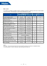
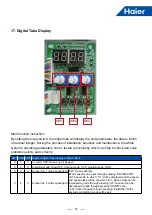
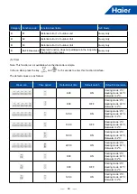
SW1 SW2 SW3
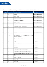
Segment digital tube display content LD2~4
0
5
0
Actual frequency of compressor(Hz): 90 means 90Hz
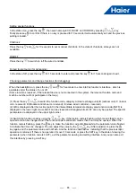
•Frequency of compressor can be set through pressing “ENTER(SW7)” with 3 seconds, in which
“111” will be displayed and the frequency showed. Frequence can be increased one Hz through
pressing “UP” once and can be decreased one Hz through pressing “DOWN” once;
•“000”will be showed through pressing “Exit(SW6)” with 3 seconds and setting mode will be exit.
0
7
0 Electronic expansion valve step (LEVa1): 90 means 90pls
0
9
0 Electronic expansion valve step (LEVa2): 90 means 90pls
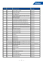
0
B
0 Valve output status:
LD2: 4WV: (0-off, 1-on); LD3: SV1: (0-off, 1-on); LD4: SV2: (0-off, 1-on)
0
C
0
High pressure switch and Low pressure switch status: LD2: High pressure switch: HPS: (0-off,
1-on) LD3: Low pressure switch: LPS: (0-off, 1-on) LD4: reserved: “-”
0
D
0 Reserved
0
E
0 Compressor electrical heater output:
LD2: CH1: (0-off, 1-on);LD3: BH:(0-off, 1-on); LD4: reserved: “-”
0
F
0 Software version:“1.0”means Ver1.0.
0
0
1
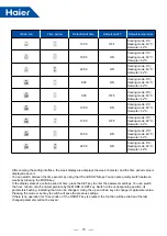
Pd: Pressure of discharge:unit: kg, a decimal fraction
0
2
1
Ps: Pressure of suction: unit: kg, a decimal fraction
0
3
1 Td: discharge temperature : (unit:°C)
0
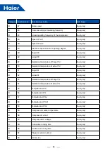
5
1 Tdef: defrost temperature: (unit:°C)
0
7
1 Toil: oil temperature: (unit:°C)
0
9
1 Tc: condensing temperature (unit:°C)
0
E
1 Ts: suction temperature (unit:°C)
0
1
F Tao Tao: ambient temperature (unit:°C)
0
2
F Pd_temp:condensing temperature (unit:°C)
0
4
F Ps_temp: evaporate temperature (unit:°C)
0
5
F
Tliqsc (unit:°C)
0
6
F Tsco (unit:°C)
0
8
F Operating time of compressor: Unit: hour
0
A
F
Operating current of compressor: unit: A, a decimal fraction
0
B
F
Unit current: CT: unit: A, a decimal fraction
0
C
F Direct current voltage of Invertor comperssor: unit: V
0
E
F Invertor module temperature of compressor: (unit:°C)
0
0
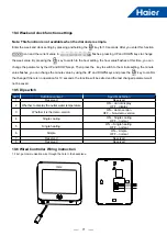
7 Outlet water temperature Two (°C)
0
0
8 Ref Rerigerate gas pipe temperature Tho (°C)
0
0
9
Refrigerate liquid pipe temperature Thi (°C)
0
0
B Inlet water temperature Twi (°C)
0
0
C
Hydraulic features:No.1: water flow switch (0-cut off, 1-connected) No.2: Pump status (0-off,
1-on);No.3:Electrical heating (0-off, 1-on)
(i.e. “110” means water flow switch is closed, pump is on and Electrical heating is off)
0
0
D
Hydraulic features:No.1: supply water flow switch (0-cut off, 1-connected)
No.2: unit on/off signal(0-off, 1-on);No.3: Floor heating valve output status (0-off, 1-on) (i.e. “001”
means supply water flow switch is connected,Indoor unit on/off signal is off and Floor heating
valve output status is on.)
Summary of Contents for AU082FYCRA(HW)
Page 1: ...ATW Service Manual SYJS 03 2019REV A Edition 2019 03 ...
Page 11: ...9 405 410 600 174 174 450 950 965 395 6 Dimensions AU082FYCRA HW Unit mm ...
Page 12: ...10 AU112 162FYCRA HW Unit mm 1490 950 380 187 405 410 600 174 174 450 170 ...
Page 13: ...11 AU082FYCRA HW 7 Piping Diagram ...
Page 14: ...12 AU112 162FYCRA HW ...
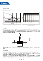
Page 27: ...25 12 Water Pressure Drop ...
Page 28: ...26 ...


